
Injection device

a technology of injection device and injection needle, which is applied in the direction of ampoule syringe, intravenous device, infusion needle, etc., can solve the problems of needle cap not being put back, safety risks, uncomfortable or difficult manual actuation of syringe for certain patients, etc., and achieves the effect of simple and safe us

Pending Publication Date: 2022-01-20
ARES TRADING SA
View PDF0 Cites 0 Cited by
  • Summary
  • Abstract
  • Description
  • Claims
  • Application Information

AI Technical Summary

Benefits of technology

The invention is about an injection device that is easy to use and reduces the risk of manipulating the medicine container in a way that could be false. The device includes a plunger actuation mechanism that is connected to a motor and engages the syringe to pull the plunger back, making it easy to insert the syringe into the device. The device also has a cradle that matches the shape of the syringe and a flexible clip arm to hold the syringe in place. This allows for easy and flexible orientation of the syringe in the device, and also allows for rotational differences between the syringe and the device without needing to align the flanges.

Problems solved by technology

However, manual actuation of a syringe is often uncomfortable or difficult for certain patients and there are also safety risks associated with the needle cap not being put back properly over the needle after use of the syringe.
Such systems however have similar drawbacks as the custom medicine container devices as the injection device only accepts the particular syringe.
Both such specific syringes as well as custom medicine containers are often limited to a specific manufacturer or a specific medication, and the device may not be used with the delivery of medication from different manufacturers.
Further, automated injection devices that receive cartridges require a needle that may only be used once and therefore needs to be provided in a disposable part, which often requires various steps to operate the device.
In addition, ensuring the sterility prior to use may also be an issue when using such injection devices.
Although automated injection devices are convenient for self-injection by a patient all of the aforementioned drawbacks result in high costs and increased risk of user error.

Method used


Image

  • Injection device
  • Injection device
  • Injection device

Examples


Embodiment Construction

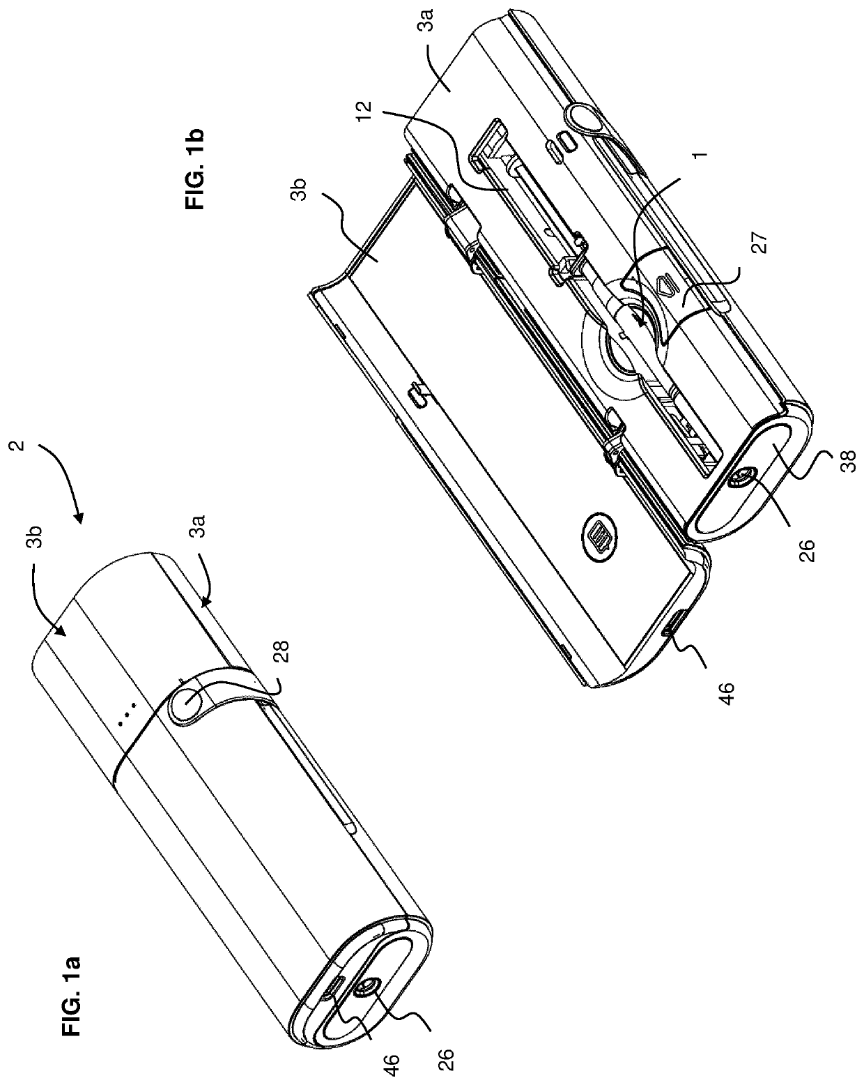
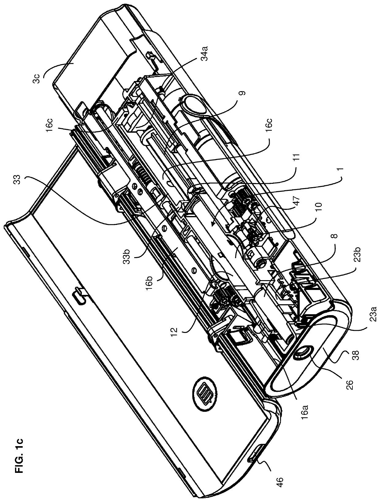
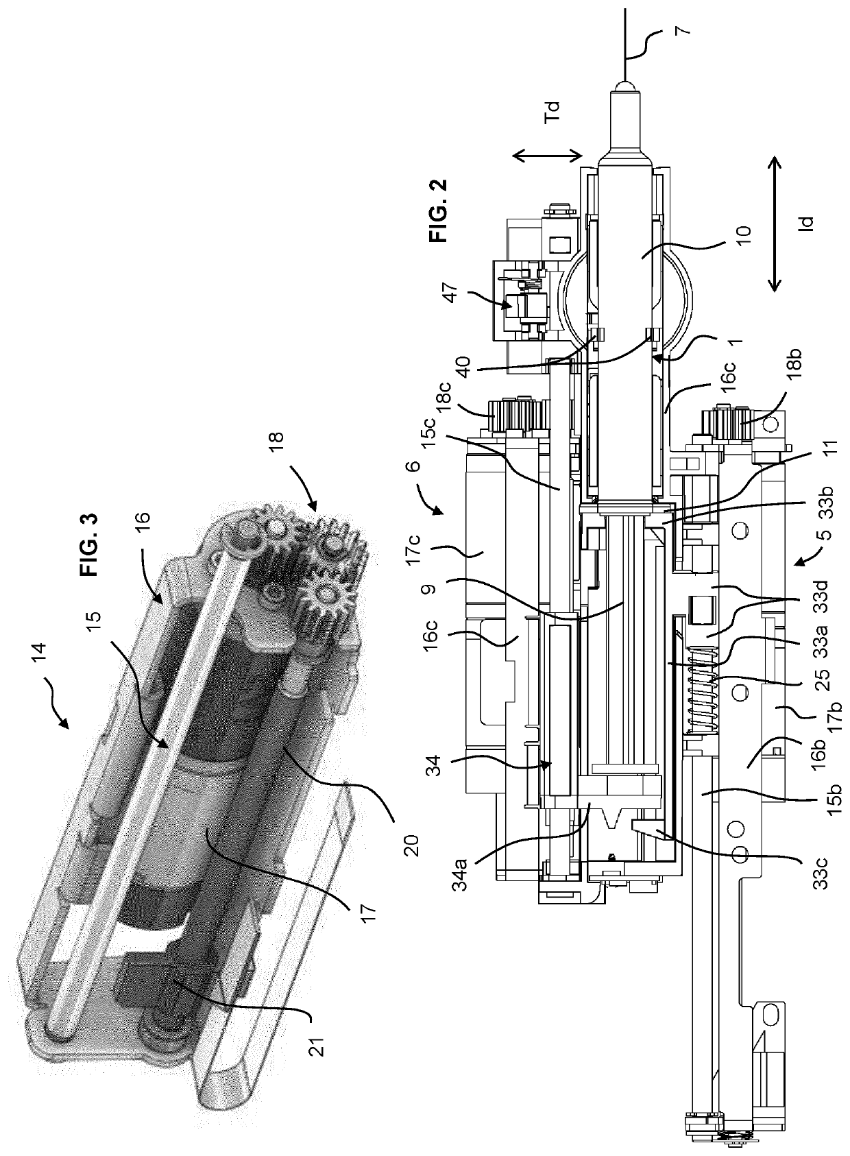
[0047]Referring to the figures, an injection device 2 according to an embodiment of the invention comprises a housing 3 having a base portion 3a and lid portion 3b. The base 3a comprises a syringe cradle 12 for lodging therein a syringe 1. The syringe 1 may be a standard type of syringe that is in widespread use for manual transcutaneous injection of a liquid drug. Such transcutaneous injection may include for example subcutaneous injections. The syringe 1 comprises a needle 7, a barrel 10, possibly a glass barrel, having a flange 11, a plunger 9 for pressing the liquid out through the needle, and a needle cap 8 for covering the needle when the syringe is not in use.

[0048]The syringe cradle 12 is provided with a shape that allows insertion of the syringe 1 into the base 3a, the shape of the cradle being configured to conform to the shape of the syringe with a certain amount of play in order to allow easy insertion of the syringe in the cradle in the correct orientation. In particula...


PUM


Abstract

Injection device (2) comprising a housing (3), a syringe cradle (12) for removably receiving a syringe (1) having a needle (7), a container (10) with a flange (11), a plunger (9) and a removable needle cap (8) in the housing, and a system for performing automated injection comprising: —a cap actuation mechanism (4) for gripping, storing and retrieving the needle cap, —a syringe actuation mechanism (5) for moving the syringe in an injection direction (Id) from a position where the needle is inside the housing to an injection position where the needle projects out of a needle port of the housing on a skin contact face of the housing, and —a plunger actuation mechanism (6) for advancing the plunger for administration of the liquid drug.

Description

FIELD OF THE INVENTION[0001]The present invention relates to an automated injection device.BACKGROUND[0002]Many drugs are provided in syringes (pre-filled syringes) that are manually actuated, the syringe comprising a container with a needle and a plunger rod to expel the drug. The advantages of such standard pre-filled syringes are their widespread availability and the large range of medications that may be conditioned in such syringes. However, manual actuation of a syringe is often uncomfortable or difficult for certain patients and there are also safety risks associated with the needle cap not being put back properly over the needle after use of the syringe.[0003]In order to provide an alternative and improve the ease of administration of a liquid drug to a patient automated or auto-injection devices have become very popular. Automated injection devices often are more convenient to operate by non-trained individuals such as for example a patient. However, such automated injectio...

Claims


Application Information

Patent Timeline
Patent Type & Authority Applications(United States)
IPC IPC(8): A61M5/20A61M5/32A61M5/315
CPCA61M5/2033A61M2005/206A61M5/31576A61M5/3204A61M5/1452A61M5/20A61M5/28A61M2005/3215
Inventor LE MASNE, QUENTINLEWIS, SCOTT ALEXANDERO'SHEA, MACDARA EAMONNSHAW, THOMAS HENRYBYATT, DOUGLAS EDWARD CAMPBELL
Owner ARES TRADING SA
Learn More