Device for amplifying the current of an abnormal electrical discharge and system for using an abnormal electrical discharge comprising one such device

a technology for amplifying the current of abnormal electrical discharges and abnormal electrical discharges, which is applied in the direction of vacuum evaporation coatings, plasma techniques, coatings, etc., can solve the problems of increasing the the system is not in widespread use today, and the interdependence of voltage and ionic current is a constraint on such devices. to achieve the effect of increasing the ionic curren

Inactive Publication Date: 2007-02-27
TECMACHINE SA
View PDF5 Cites 0 Cited by
  • Summary
  • Abstract
  • Description
  • Claims
  • Application Information

AI Technical Summary

Benefits of technology

[0050]The plasma amplifier according to the invention has many advantages. In particular, the plasma amplifier increases the ionic current on the substrate carrier by a factor from 1 to 10 compared to the current normally obtained with conventional magnetron cathode sputtering. The factor depends on the current imposed on the amplifier (from 0 to 1.5 times the cathode current).
[0051]The invention also has other advantages that are particularly beneficial for the user: the ionic current from the plasma amplifier can be adjusted independently of that from the primary source. Also, the bias voltage and the current of the substrate carrier can be adjusted independently, so that it is possible to control independently the number and the energy of the ions bombarding the substrate.

Problems solved by technology

One constraint imposed on such devices is the interdependence of the voltage and the ionic current.
However, increasing the voltage can quickly become a problem, as ions with too much energy can create unwanted modifications of the surface of the substrate to be treated, coated or modified.
Such systems are not in widespread use today, mainly because they are difficult to use and unreliable.
Furthermore, the prior art systems cannot, without great difficulty if at all, be produced with different geometries and different sizes, in order to cater for a large number of industrial configurations.

Method used


Image

  • Device for amplifying the current of an abnormal electrical discharge and system for using an abnormal electrical discharge comprising one such device
  • Device for amplifying the current of an abnormal electrical discharge and system for using an abnormal electrical discharge comprising one such device

Examples


example

[0060]In a 350 mm diameter vacuum deposition machine, a 150 mm diameter magnetron cathode is installed and supplied with a power of 1800 W at a voltage of 550 V (3.3 A). The plasma amplifier receives a supply current of 4 A. The rotating substrate carrier is biased to a voltage of −100 V. The bias current Ib is measured.

[0061]The magnetic field at the surface of the amplifier is 11. 10−2 Tesla.

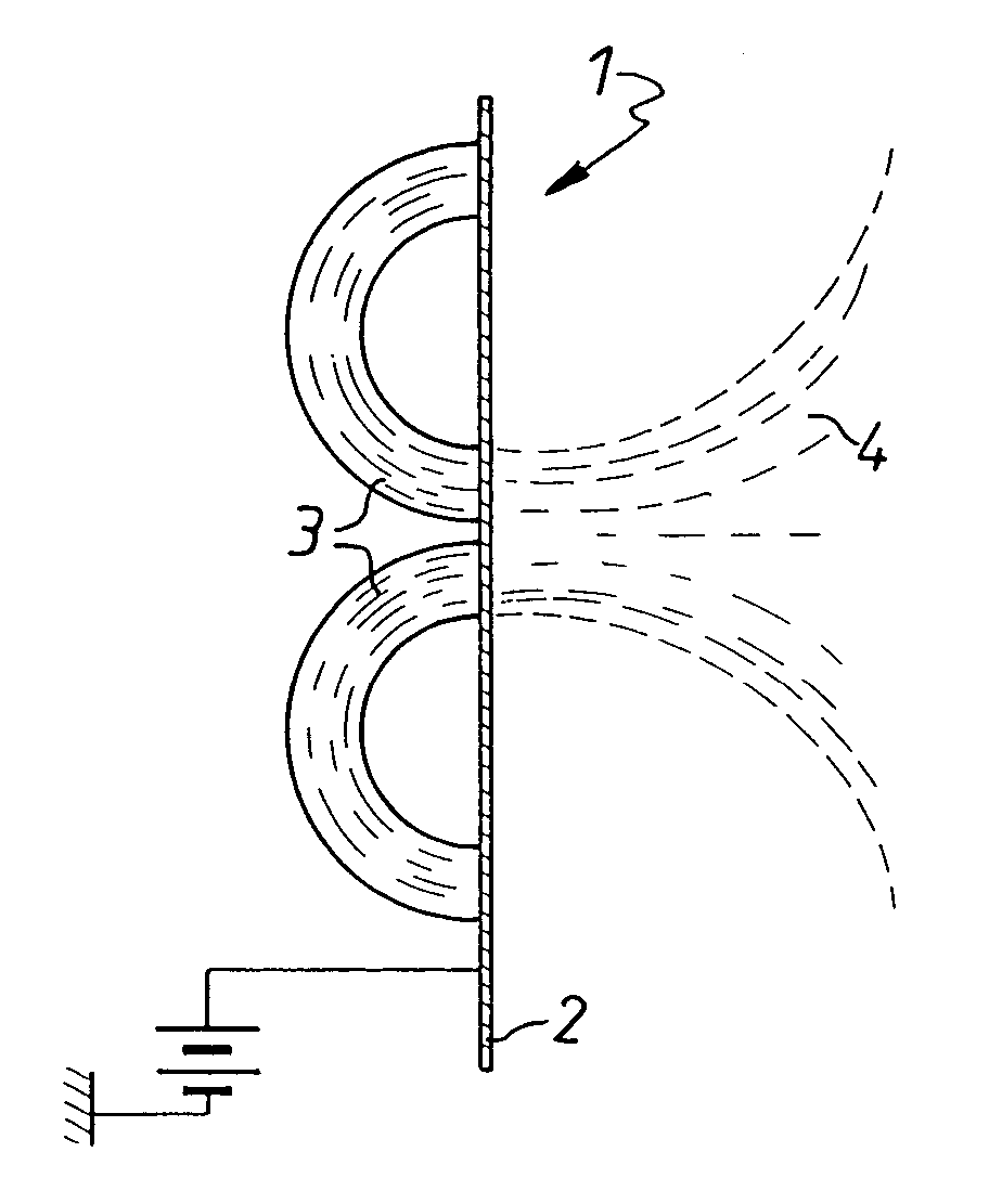
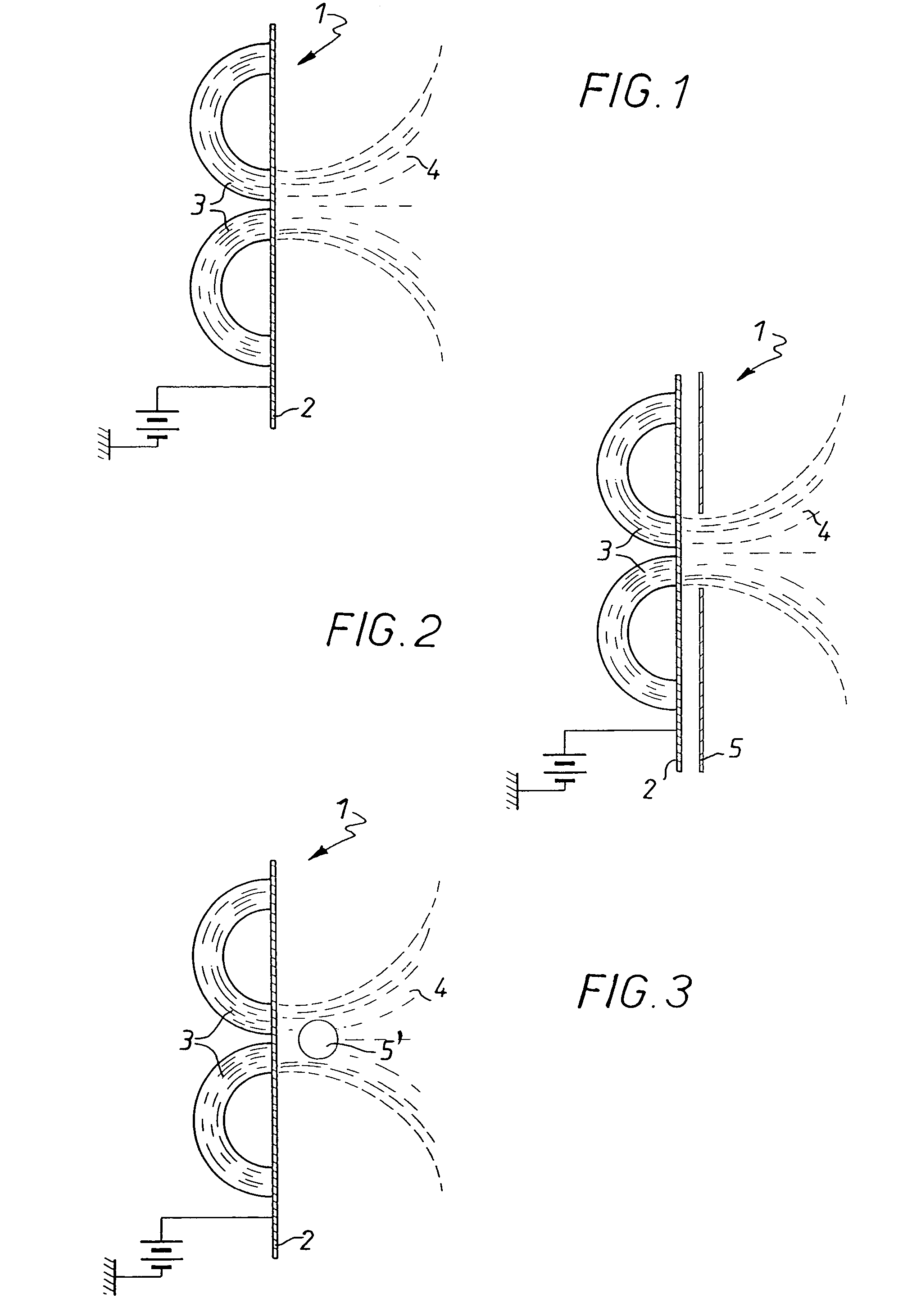
[0062]The electrode is a 150 mm diameter disk.

[0063]The ion acceleration voltage V is measured with and without the plasma amplifier according to the invention (configuration 0 and configuration 1, respectively).

[0064]The efficacy of the system is characterized by the factor k, the ratio of the current IbA collected on the parts when the plasma amplifier is operating and the current Ib received when there is no plasma amplifier.

[0065]The results are indicated in Table I below.

[0066]

TABLE IPlasmaV in voltsamplifieron substrateConfigurationpresentk = IbA / Ibcarrier0 (comparative)No1−1001Yes6.2−10...


PUM

PropertyMeasurementUnit
magnetic fieldaaaaaaaaaa

Abstract

A device (1) for amplifying the current of an abnormal electrical discharge, characterized in that it comprises an electrode which is positively polarized (2) and associated with a magnetic circuit (3) producing a magnetic field (4) which is uniformly divergent, whereby the intensity on the surface of the electrode is more than approximately 6.102 Tesla, the electrode being positioned in the region where the magnetic field is at its most intense.

Description

BACKGROUND OF THE INVENTION[0001]The present invention relates to a device for amplifying the current of an abnormal electrical discharge and a system for using an abnormal electrical discharge comprising one such device.[0002]The invention relates to all devices for using the current of an abnormal electrical discharge, also known as a luminescent discharge, further known as a cold plasma, in particular for making deposits on, treating and modifying the surface of a metal or non-metal substrate.[0003]Luminescent discharges are increasingly used as a material and / or energy transfer medium in many surface modification processes; processes for coating metal or non-metal parts may be cited, and among these magnetron cathode sputtering, plasma-enhanced chemical deposition, assisted thermochemical treatment processes such as post-discharge (deferred plasma) or ionic nitriding, ionic etching processes, plasma cleaning, etc. These techniques are used in most industrial fields, especially m...

Claims


Application Information

Patent Timeline
Patent Type & Authority Patents(United States)
IPC IPC(8): C23C14/35C23C16/00H01J37/34
CPCH01J37/3405H01J37/3266
Inventor HEAU, CHRISTOPHETERRAT, JEAN-PAUL
Owner TECMACHINE SA
Why Eureka
Try Eureka