
Apparatus for withdrawing sprayed paint and withdrawal plate suitable therefor

Active Publication Date: 2022-01-27
LEE MYOUNG JONG
View PDF0 Cites 0 Cited by
  • Summary
  • Abstract
  • Description
  • Claims
  • Application Information

AI Technical Summary

Benefits of technology

The present invention aims to solve problems in the conventional painting process by reducing paint material cost and facility cost, while simultaneously reducing the formation of sludge and contamination water. The invention achieves this by withdrawing and reusing paint discarded without using water, and providing an apparatus for withdrawing sprayed paint. These technical effects provide lower costs and improved operational efficiency, as well as the reduction of environmental contamination.

Problems solved by technology

In this case, the water and a sprayed dust state paint are mixed to fall to the bottom, resulting in a sludge, which causes a malfunction of a circulating pump, etc.
Further, in the case of the sludge of the mixture of the paint and the water, it is difficult to treat contaminated water, large processing cost is generated, and the sludge is intractable.
In addition, the water-paint mixture sludge is sticky and thus hardened in a form like rice cake, and as a result, it is difficult to treat the sludge, resulting in suffering a difficulty in maintenance of a facility and taking a lot of time for the maintenance and causing facility maintenance cost to increase.
Further, in the conventional case, as a sprayed paint material is attached to an inner wall of the booth, it is very difficult to clean the sprayed paint material and an operation of the facility should be stopped, so there is a problem that productivity is lowered.

Method used


Image

  • Apparatus for withdrawing sprayed paint and withdrawal plate suitable therefor
  • Apparatus for withdrawing sprayed paint and withdrawal plate suitable therefor
  • Apparatus for withdrawing sprayed paint and withdrawal plate suitable therefor

Examples


Embodiment Construction

[0033]Hereinafter, the present invention will be additionally described together with the accompanying drawings.

[0034]First, the present inventor has filed another Korean patent application No. 10-2019-0128050 having a title of “Painting Booth Being Possible to Reutilize by Withdrawing of Sprayed Paint” on Oct. 15, 2019, relating to the present invention, and the contents of the invention which was previously filed (hereinafter, referred to as a ‘previously filed invention’) constitute a part of a specification of the present application as they are.

[0035](‘Previously Filed Invention’)

[0036]First, with reference to FIGS. 1 to 5, the inventor's ‘previously filed invention’ related to the present invention will be described in detail.

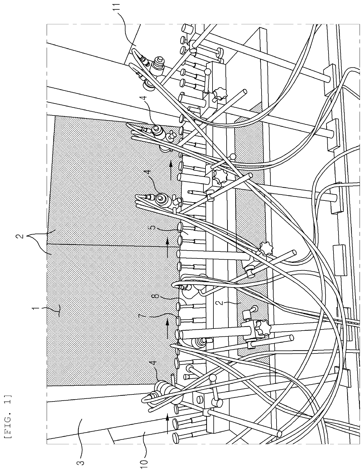
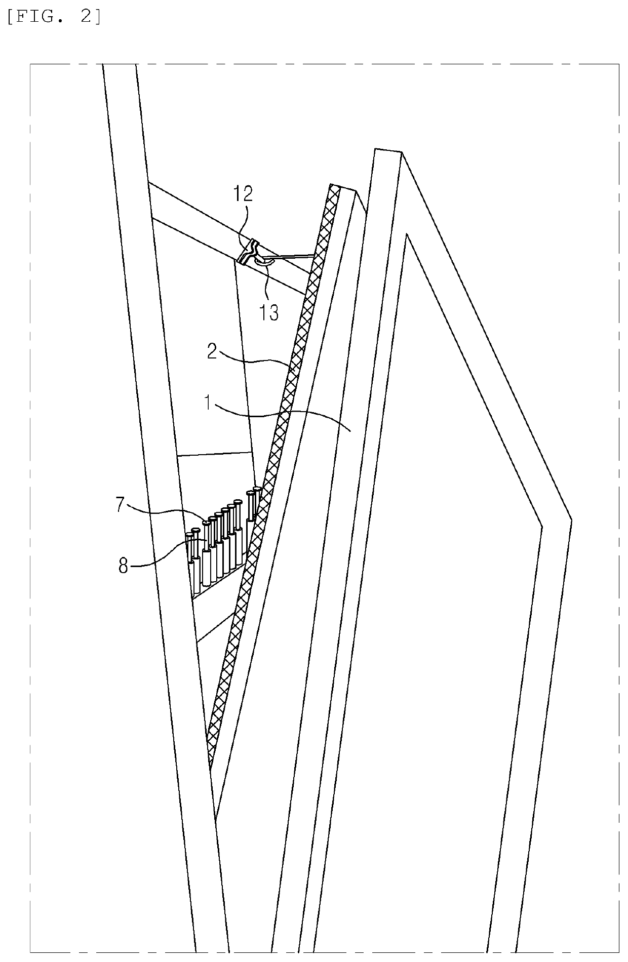
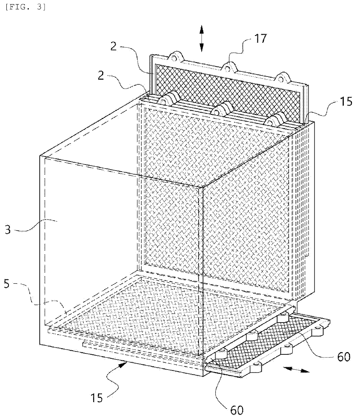
[0037]FIG. 1 illustrates one embodiment of a painting booth according to a previously filed invention, FIG. 2 is a diagram illustrating a state in which a front wall 1 portion of the painting booth is bent back and opened, and FIG. 3 is a configuration di...


PUM


Abstract

The present invention relates to a withdrawal plate suitable for an apparatus for withdrawing a sprayed paint to solve a failure of a painting facility and a contamination problem due to paint sludge, which includes: a square frame constituted by left and right side frames 91, an upper frame 92, and a base frame 93; and slats 94 arranged at a predetermined interval within the square frame, in which the left and right side frames 91 facing each other are included in one direction, and the slat 94 is fixed the left and right side frames 91 in an oblique state so that a front is lifted up and moves down backwards when viewed from the side, and multiple slats are consecutively arranged at a predetermined interval in a vertical direction.

Description

CROSS-REFERENCE TO RELATED APPLICATIONS[0001]This application claims the priority of Korean Patent Application No. 10-2020-0091728 filed on Jul. 23, 2020, in the Korean Intellectual Property Office, the disclosure of which is incorporated herein by reference.BACKGROUND OF THE INVENTIONField of the Invention[0002]The present invention relates to an apparatus for withdrawing a sprayed paint, which can withdraw a paint by spraying the paint in a painting booth for painting coating on a product surface, in particular, a small article, for example, a lid of a cosmetic container, and reutilize the withdrawn paint prevent air pollution and surrounding contamination, and a withdrawal plate suitable therefor.Description of the Related Art[0003]In a painting booth, when spray painting on an outer surface of a predetermined article, for example, in a process of spraying a painting paint on the outer surface of a product such as a lid of a container, a conventional painting booth is installed o...

Claims


Application Information

Patent Timeline
IPC IPC(8): B05B14/44B05B16/40
CPCB05B14/44B05B16/40Y02P70/10B05B13/0235B05B13/0278B05B14/412B05B14/43B05B16/90B08B3/08B08B3/106B08B1/165B08B1/20B05B14/00B05B14/30B05B14/20B05B14/41B01D46/681B01D46/10B01D46/18Y10S55/46
Inventor LEE, MYOUNG JONG
Owner LEE MYOUNG JONG
Learn More