

Cylinder
- Summary
- Abstract
- Description
- Claims
- Application Information
AI Technical Summary
Benefits of technology
Problems solved by technology
Method used
Image

Examples
second embodiment
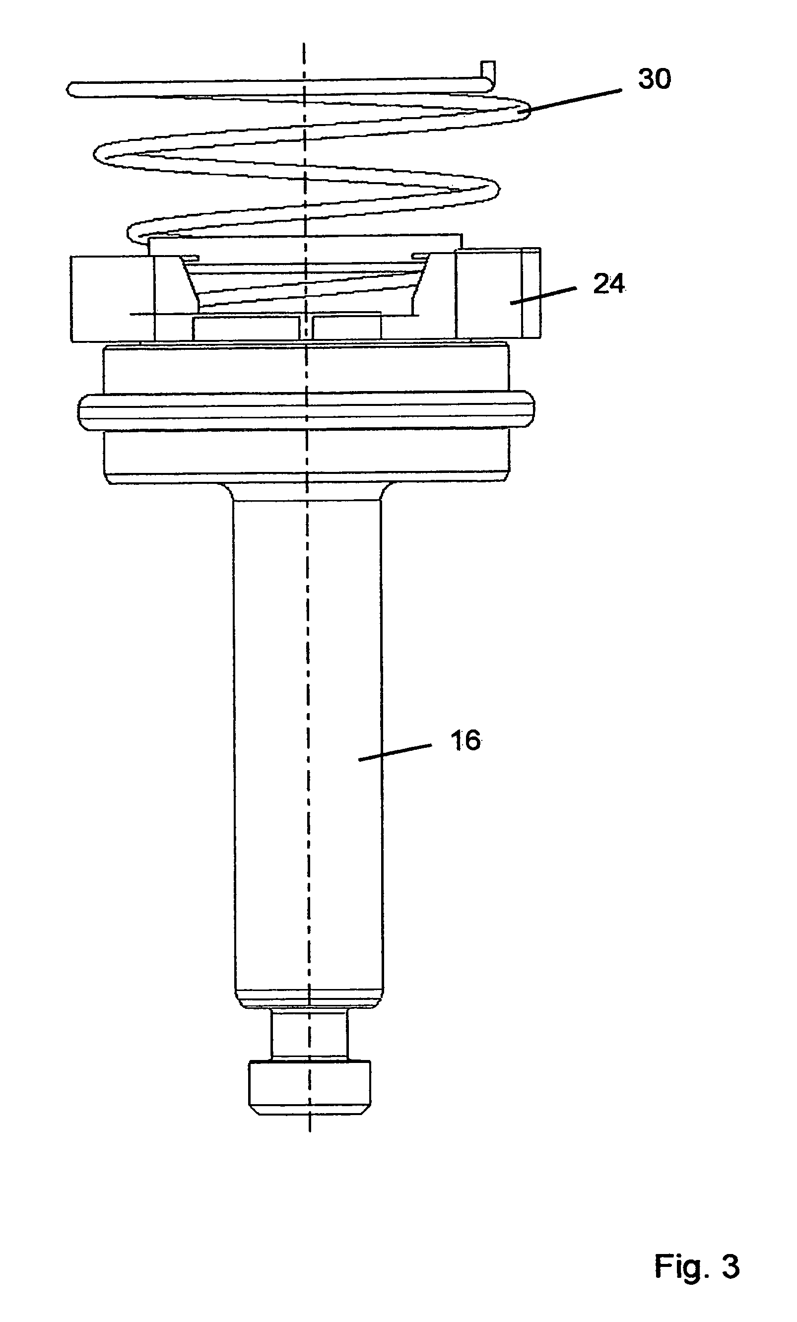
[0032]FIG. 3 shows the components of a cylinder according to the invention. In this embodiment, unlike in the embodiment according to FIG. 2, the cylinder rod 16 reaches through neither the adapter 24 nor the helical spring 30. In both embodiments, both according to FIG. 2 and according to FIG. 3, the adapter 24 with the sensor magnet 20 and the helical spring 30 are arranged in the cylinder housing 12. As an alternative, however, it is also possible to arrange the adapter 24 and the helical spring 30 outside the cylinder housing 12.
[0033]FIG. 4 shows a further embodiment of a cylinder according to the invention, the cylinder housing 12 having been omitted for the sake of clarity. The cylinder rod 16 reaches through the adapter 24, which secures the circular segment-shaped sensor magnet 20. To this end, the adapter 24 has a sensor-magnet receptacle 36 and a clamping projection 38. The sensor magnet 20 is received in the sensor-magnet receptacle 36 and is held fixedly by the clamping...
first embodiment
[0037]FIG. 5 shows a cross section through the cylinder 10, the inner components of which are shown in FIG. 4. It can be seen that the guide sleeve 44 is attached to an end of the cylinder housing 14 and is sealed with respect to the latter by way of an O-ring 48. In FIG. 5, the rubber seal 34 is attached directly to the piston 14. However, it is also conceivable that the rubber seal 34 is attached to the adapter 24. In addition, it is possible that, as in the first embodiment described, the adapter 24 can be turned relative to the piston 14, with the result that the piston can rotate in the cylinder housing 12, without the sensor magnet 20 being removed from its position opposite the sensor element 22. In addition, it is possible that the adapter 24 represents an integral constituent part of the piston 14.
[0038]As a result of the guide lug 42 engaging into the guide groove 40 of the adapter 24, the cylinder rod 16 can rotate freely in relation to the cylinder housing, and the senso...
PUM
 Abstract
Description
Claims
Application Information