Ejector Unit For A Road Milling Machine Or The Like
Active Publication Date: 2010-09-30
WIRTGEN GMBH
View PDF10 Cites 8 Cited by
Summary
Abstract
Description
Claims
Application Information
AI Technical Summary
This helps you quickly interpret patents by identifying the three key elements:
Problems solved by technology
Method used
Benefits of technology
[0008]It is an object of the invention to make available an improv
Problems solved by technology
The ejectors are subject to severe abrasive attack, and must therefore be regularly checked an
Method used
Image
Click on the blue label to locate the original text in one second.
Reading with bidirectional positioning of images and text.
Examples
Example
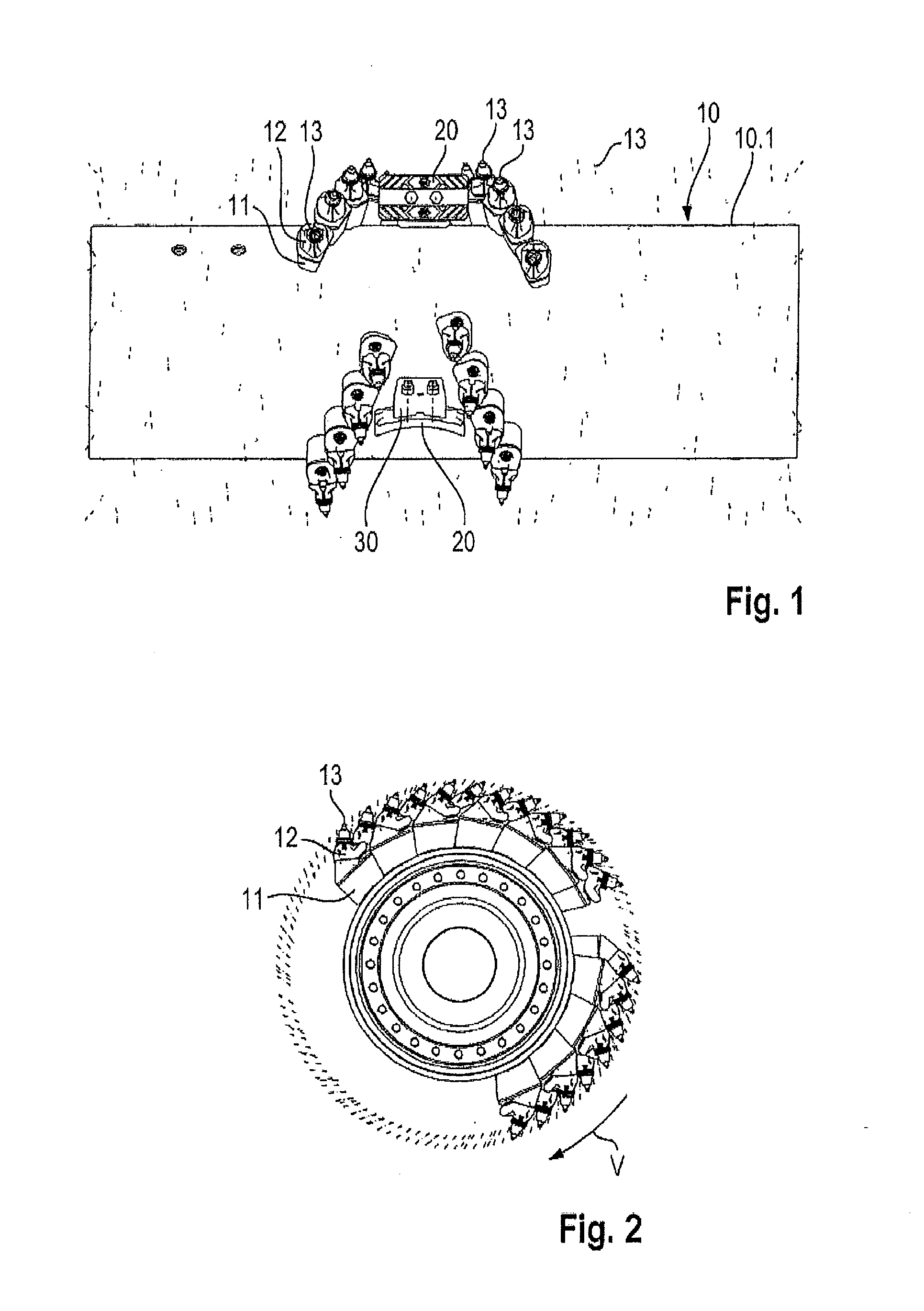
[0044]FIG. 1 shows a milling drum having a cylindrical milling tube 10 onto whose drum surface 10.1 are welded a plurality of base parts 11 of bit holder changing systems. Base parts 11 carry replaceable bit holders 12. A cutting bit 13, specifically a round-shaft cutting bit, is replaceably received in each bit holder 12. Base parts 11 are arranged with respect to one another so that they form a helix, specifically a transport helix. The helix rotates, proceeding from the side of milling tube 10 on drum surface 10.1, toward the milling tube center formed between the two sides. For better clarity, only some of the bit holder changing systems are depicted in FIGS. 1 and 2. Dashed lines that represent the center longitudinal axis of cutting bits 13 are shown as substitutes for the bit holder changing systems (not shown). As is evident from these lines, multiple transport helices are located on either side of the milling tube center.
[0045]The transport helices meet in pairs in the regi...
PUM
Property
Measurement
Unit
Angle
aaaaa
aaaaa
Angle
aaaaa
aaaaa
Angle
aaaaa
aaaaa
Abstract
The invention relates to an ejector unit, in particular for a road milling machine, having an ejector that is replaceably mounted on a carrier. In one aspect the ejector is curved in a scoop-like fashion. In another aspect the ejector is reversible upon the carrier to allow the ejector to be reversed after one wear surface is worn, thus presenting a new second wear surface.
Description
[0001]We, Karsten Buhr, a citizen of Germany, residing at Willroth, Germany, Stefan Abresch, a citizen of Germany, residing at Dierdorf, Germany, Thomas Lehnert, a citizen of Germany, residing at Oberraden, Germany, Guenter Haehn, a citizen of Germany, residing at Koenigswinter, Germany, and Cyrus Barimani, a citizen of Germany, residing at Koenigswinter, Germany have invented a new and useful “Ejector Unit For A Road Milling Machine Or The Like”. This application claims priority from German Patent Applications No. 10 2009 014 730.6-25 and No. 10 2009 014 729.2-25, both filed Mar. 25, 2009.BACKGROUND OF THE INVENTION[0002]1. Field of the Invention[0003]The invention relates to an ejector unit, in particular for a road milling machine, having an ejector that comprises a conveying surface.[0004]2. Description of the Prior Art[0005]Road milling machines usually comprise a milling tube on whose surface are mounted a plurality of bit holders. The bit holders are usually part of a bit hol...
Claims
Application Information
Patent Timeline
Application Date:The date an application was filed.
Publication Date:The date a patent or application was officially published.
First Publication Date:The earliest publication date of a patent with the same application number.
Issue Date:Publication date of the patent grant document.
PCT Entry Date:The Entry date of PCT National Phase.
Estimated Expiry Date:The statutory expiry date of a patent right according to the Patent Law, and it is the longest term of protection that the patent right can achieve without the termination of the patent right due to other reasons(Term extension factor has been taken into account ).
Invalid Date:Actual expiry date is based on effective date or publication date of legal transaction data of invalid patent.
IPC IPC(8): E21C35/20E01C23/12
CPCE01C23/088B28D1/188E01C23/127
Inventor BUHR, KARSTENABRESCH, STEFANLEHNERT, THOMASHAEHN, GUENTERBARIMANI, CYRUS