Fluid mixing unit and fluid mixing method

Pending Publication Date: 2022-02-03
JGC CORP
View PDF0 Cites 0 Cited by
  • Summary
  • Abstract
  • Description
  • Claims
  • Application Information

AI Technical Summary

Benefits of technology

The invention is a container that has two separate spaces inside it. The container is made up of a porous body that separates the two spaces. The fluid is then supplied to both spaces in a way that ensures it is evenly distributed. The container also has closing members that create a meandering flow, which allows the fluids to stay in contact with each other for a longer period of time. This mixing process results in a mixed fluid where the concentration of the other fluid is gradually increased. Overall, this invention allows for reliable mixing of fluids and creates a more uniform mixture.

Problems solved by technology

However, an apparatus which performs the batch production is configured to perform such steps, so that the apparatus is large in size.
Further, the operations of the apparatus, such as charging the liquid into the container and discharging the mixed liquid from which the crystals are precipitated, are complicated.
For this reason, according to the batch production, the production cost of the product is increased, which is a concern.
However, when the pipe diameter is small as described above, the loss of pressure received by each liquid flowing through the pipe is large.
Namely, it is difficult to increase the flow speed of each liquid flowing in the apparatus, and each liquid flows as a laminar flow through a flow path in the apparatus, so that the laminar flows are unlikely to mix with each other in the flow path.
For this reason, even when the liquids are supplied to the flow path (flow space) which is common, and are mixed with each other in the flow path, sufficient mixing cannot be performed, which is a concern.
The case of performing crystallization has been described as an example; however, even when a process of mixing liquids other than crystallization (specific examples will be described in the section of the mode for carrying out the invention) is performed, the same problem exists.
However, according to such a mixing method, the liquids flow into the common flow path at once, so that the above-described rapid reaction occurs, which is a concern.

Method used


Image

  • Fluid mixing unit and fluid mixing method
  • Fluid mixing unit and fluid mixing method
  • Fluid mixing unit and fluid mixing method

Examples


first embodiment

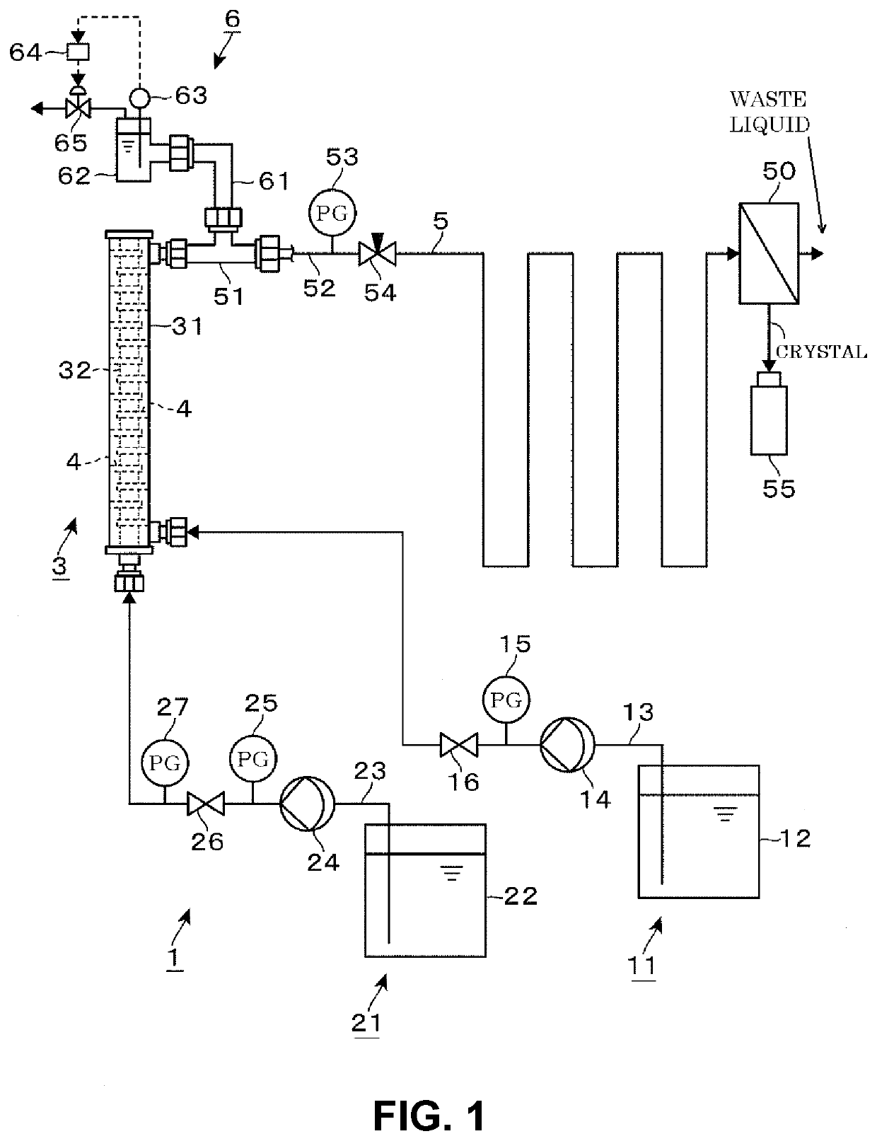
[0025]FIG. 1 illustrates a crystallizing apparatus 1 including a fluid mixing unit 3 according to the invention, and the crystallizing apparatus 1 is configured to continuously perform poor solvent crystallization. The crystallizing apparatus 1 includes a raw material liquid supply unit 11, a poor solvent supply unit 21, the fluid mixing unit 3 that mixes a raw material liquid and a poor solvent to create a mixed liquid (mixed fluid), an aging pipe 5 that precipitates crystals of a target substance from the mixed liquid flowing out from the fluid mixing unit 3 to cause the crystals to grow, a solid and liquid separating unit 50 that separates the crystals which have grown in the aging pipe 5, and an exhaust unit 6 that traps and removes bubbles in the mixing liquid toward the aging pipe 5. In addition, the crystallizing apparatus 1 is configured as an upflow type apparatus in which the raw material liquid and the poor solvent each are supplied from a lower portion side of a processi...

second embodiment

[0051]Subsequently, the points of difference of a fluid mixing unit 7 compared to the fluid mixing unit 3 will be mainly described with reference to FIG. 8 which is a longitudinal sectional side view and FIG. 9 which is a cross-sectional plan view. In the fluid mixing unit 7, instead of providing the baffle plate 4 in the second flow space 36, a baffle plate 44 is provided in the first flow space 35. A meandering flow is formed in the first flow space 45 of the fluid mixing unit 7 by the baffle plate 44. In addition, the outlet 39 is provided in a ceiling portion of the processing container 31, and is open only to the first flow space 35 of the first flow space 35 and the second flow space 36. Then, the raw material liquid supply line 13 is connected to the bottom wall supply port 34 of the processing container 31, and the poor solvent supply line 23 is connected to the side wall supply port 33 of the processing container 31.

[0052]The baffle plate 44 is formed in substantially a ci...

third embodiment

[0055]Subsequently, the points of difference of a fluid mixing unit 8 compared to the fluid mixing unit 3 will be mainly described with reference to FIG. 10 which is a longitudinal sectional side view and FIG. 11 which is a cross-sectional plan view. As the points of difference of the fluid mixing unit 8 compared to the fluid mixing unit 3, porous membranes 32A, 32B, and 32C, first flow spaces 35A, 35B, and 35C, and bottom wall supply ports 34A, 34B, and 34C are provided, and the porous membranes 32A to 32C are provided to penetrate through the baffle plates 4. With such a configuration, different liquids can be supplied to the first flow spaces 35A, 35B, and 35C, respectively, and the liquids can be supplied to the second flow space 36 through the porous membranes 32A, 32B, and 32C, respectively.

[0056]For example, chemicals 81, 82, and 83 which are liquids are supplied from the bottom wall supply ports 34A, 34B, and 34C, respectively, and a chemical 84 which is a liquid is supplie...


PUM

PropertyMeasurementUnit
Thicknessaaaaaaaaaa
Flow rateaaaaaaaaaa
Solubility (mass)aaaaaaaaaa

Abstract

A fluid mixing unit includes a cylindrical porous body partitioning a container into a first flow space and a second flow space surrounding the first flow space. A first supply port supplies a first fluid to one of the first and second flow spaces. A second supply port provided on one end side of the container in an axial direction of the cylindrical body supplies a second fluid to the other flow space. An outlet for a mixed fluid is provided on the other end side of the container to be open only to the other flow space. Closing members are provided in a plurality of stages along the axial direction to alternately close a right and a left of the other flow space as seen in the axial direction in the other flow space. A meandering flow is formed in the other flow space to create the mixed fluid.

Description

TECHNICAL FIELD[0001]The present invention relates to a fluid mixing unit and a fluid mixing method by which a plurality of fluids are mixed in a container to create a mixed fluid.BACKGROUND[0002]In a process of producing a pharmaceutical product or the like, a process of mixing a plurality of liquids is performed. One example of the process of mixing is crystallization in which crystals of a target substance are obtained from a raw material liquid. For example, in poor solvent crystallization, a poor solvent that decreases the solubility of a target substance is mixed with a raw material liquid in which the target substance is dissolved, to precipitate crystals of the target substance in a mixed liquid obtained. In addition, in reaction crystallization, a reaction liquid which reacts with a raw material substance to create a target substance having a lower solubility is mixed with a raw material liquid which contains the raw material substance, to precipitate crystals of the target...

Claims


Application Information

Patent Timeline
IPC IPC(8): B01F5/06B01F3/08
CPCB01F5/0606B01F2005/0025B01F3/088B01F3/0865B01F23/451B01F25/313311B01F25/31421B01F25/3141B01F25/3131B01F25/4231B01F25/4233B01D9/0054B01D9/0059B01D9/0036B01F2025/91912B01F2025/93B01F2215/0431B01D9/02
Inventor KAWANO, MASAHIROTAHARA, NAOKITAKAHASHI, KIMINORIOGURO, SHUICHI
Owner JGC CORP
Why Eureka
Try Eureka