Chemical Delivery System for Water or Effluent Treatment

Active Publication Date: 2016-09-01
BRADEN MICHAEL R
View PDF4 Cites 3 Cited by
  • Summary
  • Abstract
  • Description
  • Claims
  • Application Information

AI Technical Summary

Benefits of technology

The invention aims to provide a system for disinfecting wastewater that has two main advantages. Firstly, it reduces the risk of damage to components of the system due to the use of corrosive chemicals. Secondly, it ensures that the disinfectant is more reliably in contact with all the effluent, leading to longer contact time for more of the effluent. This is in contrast to venturi-based systems where there may be uneven contact with the disinfectant.

Problems solved by technology

In many cases, the chemical is corrosive (e.g., sodium hypochlorite), which might damage components of the system not manufactured from polyvinyl chloride or similar materials.
Because the disinfectant is delivered contemporaneously with effluent entering in the tank, this generally leads to longer contact time for more of the effluent.
In venturi-based systems, however, depending on the timing and amounts of prior doses delivered to effluent volume contained within a tank, a portion of the effluent being discharged may ultimately only contact disinfectant as it passes the suction inlet of the venturi device during discharge.

Method used


Image

  • Chemical Delivery System for Water or Effluent Treatment
  • Chemical Delivery System for Water or Effluent Treatment
  • Chemical Delivery System for Water or Effluent Treatment

Examples


embodiment 20

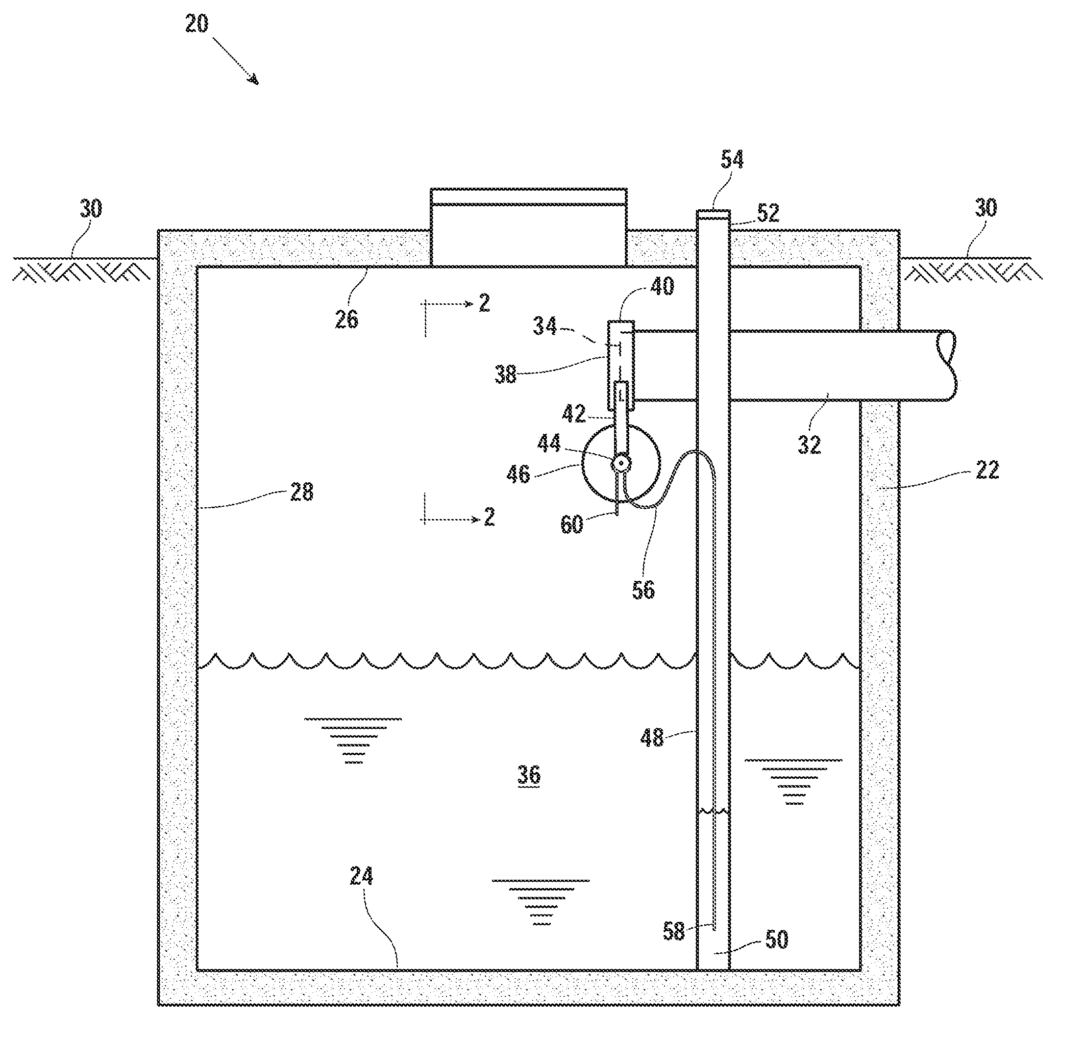
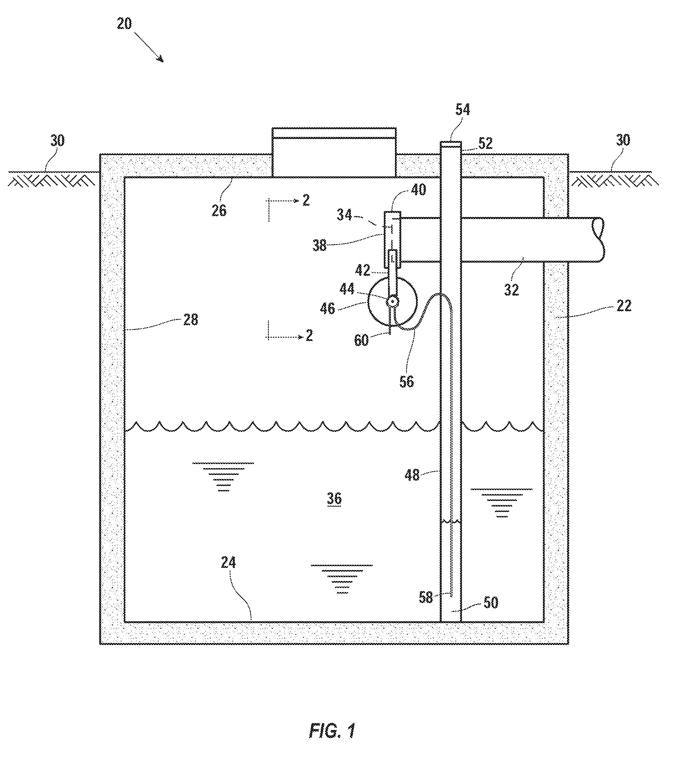
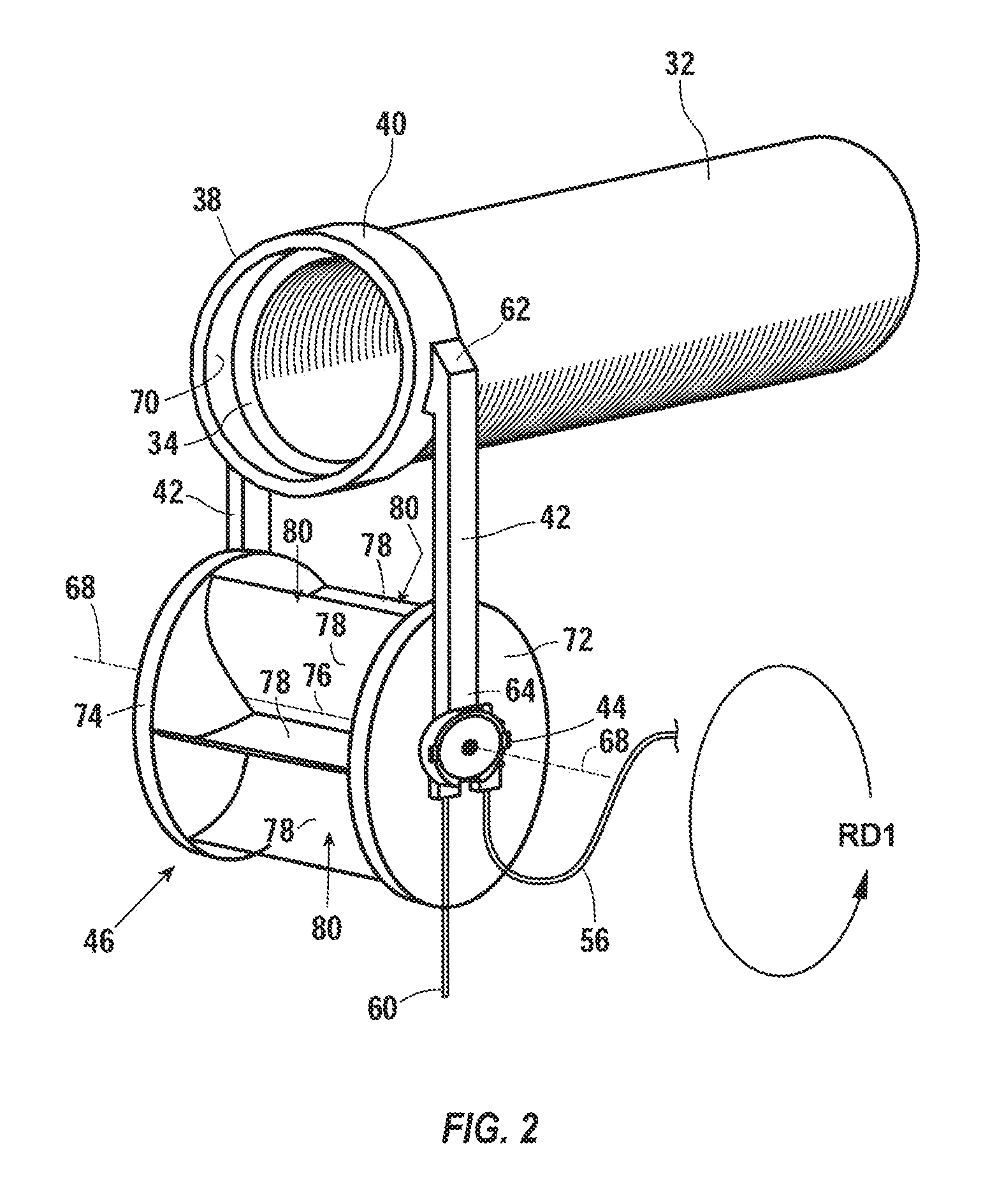
[0023]FIG. 1 shows an embodiment 20 of the invention, which includes a storage tank 22 having a bottom 24, a top wall 26, and a sidewall 28. The tank 22 is located substantially below a ground surface 30. An effluent pipe 32 is connected to an effluent source (e.g., a house or a business) and has a terminal end 34 within the tank 22. Effluent 36 periodically exits the pipe 32 and accumulates within tank.

[0024]Either periodically or when the volume of effluent 36 reaches a threshold volume, the effluent 36 may be pumped from the tank 22 through a discharge pipe to a spray field. Alternatively, the effluent 36 may migrate to an adjacent chamber (not shown) through an opening in the tank 22, from which it is disbursed through piping into a nearby leach field. These and other methods of removing effluent from a septic system are well-known to those skilled in the art and are mentioned for context.

[0025]A mounting bracket 38 is attached to the pipe 32 proximal to the terminal end 34. The...

embodiment 300

[0040]FIG. 8 shows another embodiment 300, which uses pressurized fluid (e.g., effluent) flow rather than gravity flow as described with respect to the previous embodiments. Identical numbers are used to for the same components previously described with respect to FIGS. 1-7.

[0041]In this embodiment 300, a pump 302 is connected to an end 303 of a pump discharge pipe 304. At another end 306 of the discharge pipe 304, a tank discharge pipe 307 extends to a position outside the tank 22 and terminates in a sprinkler head or drip system (not shown) for dispersal into at or near the surface 30. A return line 308 is also connected to the end 306 of the pump discharge pipe 304 and has an end 310 located above the effluent 36. A ball valve 312 is connected in line within the return line 308 to allow a system maintainer to control the amount of effluent that returns to the tank 22 when the pump 302 is activated.

[0042]A housing 316 has an inlet 318 connected (e.g., threaded to) to the end 310 o...


PUM


Abstract

A system for delivering disinfectant or other chemicals to effluent or water within a containment vessel, such as a wastewater storage tank. The invention includes a mounting bracket or housing; a rotor rotationally connected to the mounting bracket; a shaft connecting the rotor to the mounting bracket; a pump connected to the shaft, the pump having a casing and a rotor assembly; a container; and an tube having a first end within the container and a second end outside the container, a portion of the tube positioned within the pump and in contact with the rotor assembly.

Description

CROSS REFERENCES TO RELATED APPLICATIONS[0001]This application claims priority to and the benefit of U.S. provisional application Ser. No. 62 / 121348, filed Feb. 26, 2015, which is incorporated by reference / FEDERALLY-SPONSORED RESEARCH[0002]Not applicable.BACKGROUND OF THE INVENTION[0003]1. Field of the Invention[0004]This invention relates generally to a chemical delivery system that may be used, for example, to deliver a chemical (e.g., sodium hypochlorite, algaecide) to water or effluent within a containment vessel.[0005]2. Description of the Related Art[0006]Chlorinators, which use either solid or liquid disinfectants, are known to the prior art. Illustrative of chlorinators using solid disinfectants are U.S. Pat. No. 6,627,071 issued to Braden on Sep. 30, 2003; U.S. Pat. No. 6,932,912 issued to Chaffin on Aug. 23, 2005; U.S. Pat. No. 6,183,630 issued to Reeves on Feb. 6, 2001; U.S. Pat. No. 4,100,073 issued to Hopcroft on Jul. 11, 1978; U.S. Pat. No. 5,350,512 issued to Tang on ...

Claims


Application Information

Patent Timeline
IPC IPC(8): C02F1/68C02F1/50
CPCC02F1/686C02F2303/04C02F1/50C02F1/76G05D11/008
Inventor BRADEN, MICHAEL R.
Owner BRADEN MICHAEL R
Why Eureka
Try Eureka