Supercharge Your Innovation With Domain-Expert AI Agents!

Self-Modifying Apparatus For Rotational Support Structure Removal In 3D Printed Parts Using Calibrated Resonant Frequency

a self-modifying, 3d printed, support material technology, applied in the direction of chemistry apparatus and processes, cleaning using liquids, manufacturing tools, etc., can solve the problems of pre-mature failure, rough outer surface, and inability to remove support materials at a significant amount, so as to avoid or reduce bottlenecks

Active Publication Date: 2022-02-03
POSTPROCESS TECH INC
View PDF0 Cites 1 Cited by
  • Summary
  • Abstract
  • Description
  • Claims
  • Application Information

AI Technical Summary

Benefits of technology

The patent describes a method for measuring the response of a part and its support material to ultrasonic waves. Based on these measurements, the method can adjust the frequency of the ultrasonic waves to match the resonant frequency of the support material. This calibrated tuning process helps to more efficiently remove the support material, particularly for metal parts made from a single material with different densities, geometries, or porosity in the support material compared to the part. The patent also suggests an alternative to avoid or reduce the bottleneck created by manually removing support material and surface finishing additive manufactured parts.

Problems solved by technology

Removing the support material can require significant efforts.
Additionally, since additive manufacturing prints a part in discrete layers, the surface finish of a part is rough since edges of the layers do not always align with each other, thus creating a rough, bumpy outer surface.
This outer surface is not only unappealing from a visual standpoint, but also can create stress concentrations, which could develop during testing or use of the part and thus lead to a pre-mature failure.
Depending on the type of part printed, using manual labor could be cost prohibitive, and if not cost prohibitive could lead to excessive removal of material, or an uneven surface, or both.
If a surface is finished unevenly, stress concentrations could still exist, leading to pre-mature failure.
Even further, manual removal of unwanted support material and surface finishing lacks the ability to be consistent over an extended period of time.
And, such manual removal may create a bottleneck in the production process since one technician can remove support material from a small number of parts at a time.
However, these machines are limited in the type of process parameters, such as temperature, agitation level, fluid flow level, that can be altered.
They also require operation by a technician, which does not completely eliminate the bottleneck issue described above.
Additionally, if a technician is unaware that a machine is not set at the proper parameters, excessive material removal could occur, thereby ruining the part.
At the start of additive manufacturing, additive manufacturing processes were limited to making plastic parts due to the ability of plastic to be manipulated with minimal heat and pressure.
However, Goodson does not disclose a means for sensing the frequency and amplitude of the part being cleaned when ultrasonic vibrations are applied to a part within the cleaning tank, or altering the amplitude or frequency applied to the part across a plurality of time intervals.
This means that the part contained within the cleaning tank could be destroyed due to excessive cavitation if an operator is not monitoring the part closely.

Method used


Image

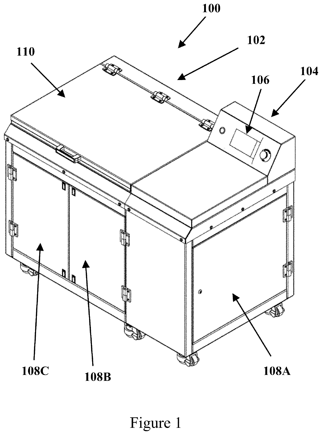
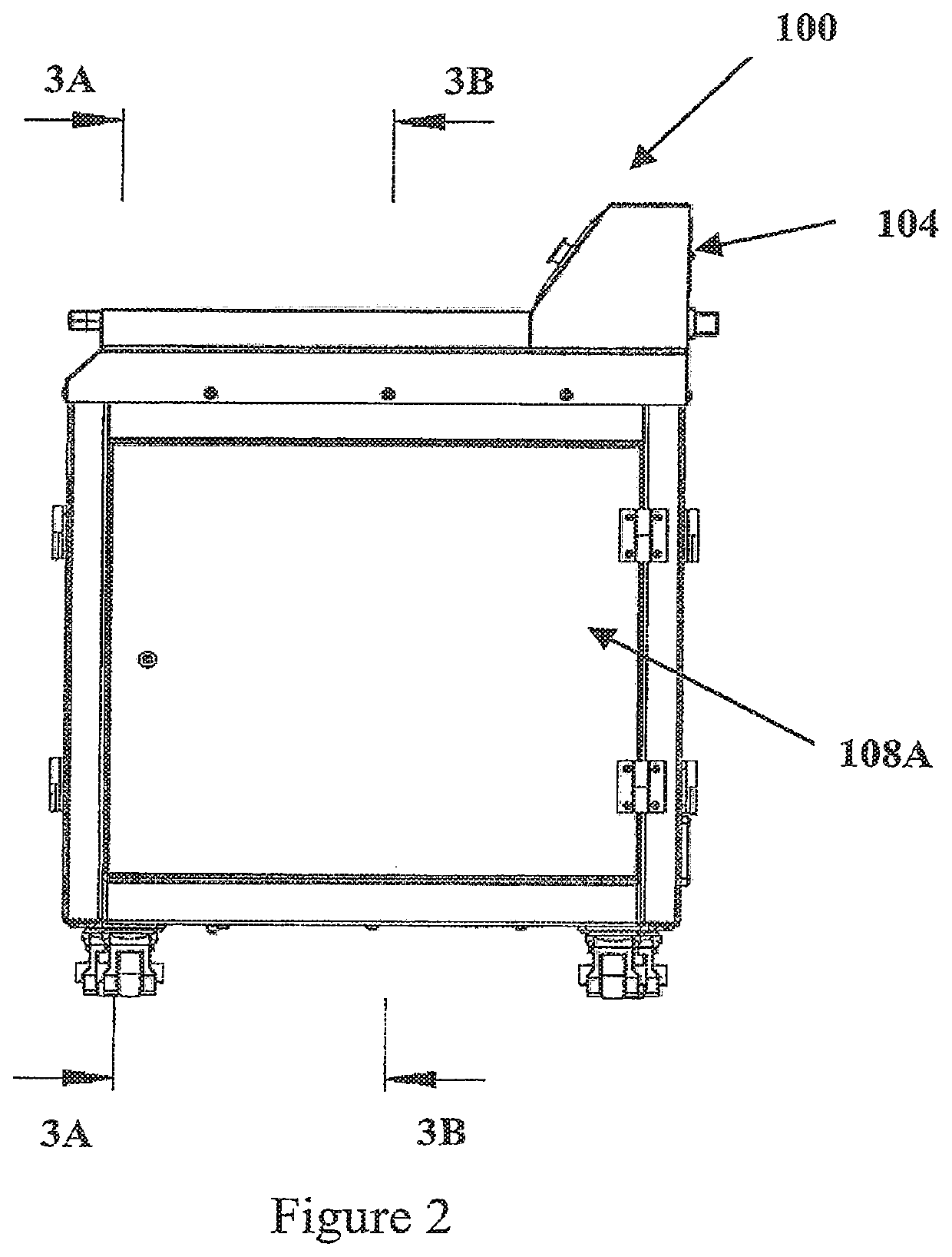
  • Self-Modifying Apparatus For Rotational Support Structure Removal In 3D Printed Parts Using Calibrated Resonant Frequency
  • Self-Modifying Apparatus For Rotational Support Structure Removal In 3D Printed Parts Using Calibrated Resonant Frequency
  • Self-Modifying Apparatus For Rotational Support Structure Removal In 3D Printed Parts Using Calibrated Resonant Frequency

Examples


first embodiment

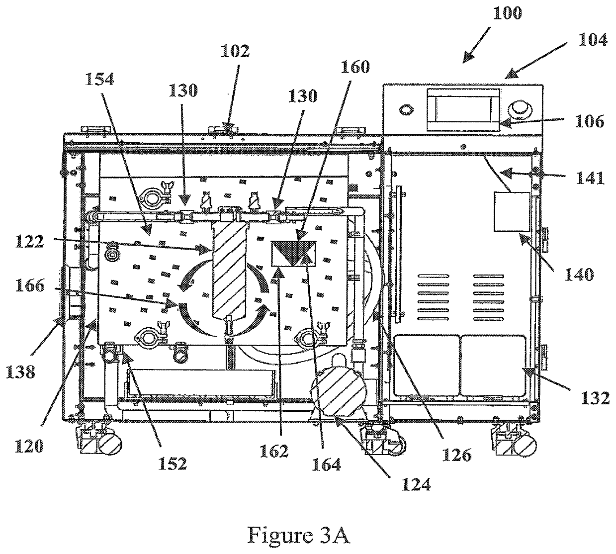
[0083]FIG. 4 is a flowchart describing optimization of a support material removal method according to the invention. Step 200 includes placing AMPHSM 160, 162 within chamber 120, and the chamber 120 has media 154 arranged within. Step 202 includes inputting a first density, geometry, material, and / or porosity of support material 162 into control unit 140. Step 204 includes measuring a set of parameters of media 154, which may include measuring temperature (via sensor 152), pH, fluid flow, agitation level, and / or pressure (via sensor 130). Step 206 includes activating pump 124 to create media vortex 166 within chamber 120. Step 208 includes agitating media 154 and AMPHSM 160, 162, which are in media 154, at a first agitation level via ultrasonic transducer 142. Step 210 incudes measuring an amplitude at which part 160 and support material 162 vibrate as a result of the first agitation level. Step 210 may be executed with the assistance of ultrasonic frequency feedback sensor (UFFS) 1...

second embodiment

[0084]FIG. 5 is a flowchart describing optimization of the support material removal method according to the invention. Step 200 includes placing the AMPHSM 160, 162 within chamber 120, and the chamber 120 has media 154 arranged within. Step 250 includes generating a run time value (“RTV”) for a duration of media vortex 166, which is generated by pump 124 circulating media 154. Step 252 includes entering the density, geometry, material, or porosity of part 160, support material 162, or both to determine an initial frequency value. The initial frequency value may be determined from a density, geometry, material, or porosity of part 160, support material 162, or both. The initial frequency value may be determined by analyzing the above parameters of the part to determine specific properties of support material 162, such as wall thickness and density, to better settle on an initial frequency value. For example, if support material 162 is solid, the initial frequency value might be set a...


PUM


Abstract

A process for removing support material from a part made by an additive manufacturing process is disclosed. The part may be arranged in a media filled tank. Ultrasonic waves are directed for the part and / or support material. Ultrasonic waves from an ultrasonic transducer are applied to a part or support material and cause the part to vibrate. The frequency of the ultrasonic energy may be tuned to cause the part and / or the support material to vibrate at its resonant frequency. The support material may have different properties, such as density, geometry, material, or porosity. Such differences may allow the support material to resonate in response to the applied ultrasonic energy waves at a different ultrasonic frequency than, the part itself.

Description

CROSS-REFERENCE TO RELATED APPLICATIONS[0001]This application is a divisional of U.S. patent application Ser. No. 16 / 348,276, filed May 8, 2019, now U.S. Pat. No. 11,110,661, which is a National Phase of International Application No. PCT / US17 / 61880, filed Nov. 15, 2017, which claims the benefit of U.S. Provisional Patent Application No. 62 / 422,198, filed Nov. 15, 2016, which applications are incorporated herein by reference in their entirety.FIELD OF THE INVENTION[0002]This invention relates generally to a method and apparatus for removing support material from parts made by additive manufacturing techniques such as 3D printing, and, more specifically, to a method and apparatus for removing support material using longitudinal waves at ultrasonic frequencies.BACKGROUND OF THE INVENTION[0003]Additive manufacturing processes (a.k.a. 3D printing) such as Selective Laser Sintering (SLS) have enabled the production of parts having complex geometries which would never be possible through t...

Claims


Application Information

Patent Timeline
Patent Type & Authority Applications(United States)
IPC IPC(8): B29C64/35B08B3/12
CPCB29C64/35B33Y40/00B08B3/12B33Y40/20
Inventor HUTCHINSON, DANIEL JOSHUA
Owner POSTPROCESS TECH INC
Features
  • R&D
  • Intellectual Property
  • Life Sciences
  • Materials
  • Tech Scout
  • Unparalleled Data Quality
  • Higher Quality Content
  • 60% Fewer Hallucinations
Learn More