
Method for control of a cylinder

a technology for controlling cylinders and pistons, applied in the direction of fluid-pressure actuator testing, mechanical equipment, servometer circuits, etc., can solve the problems of disruption of the control of blades, inability to accurately regulate the position of pistons in cylinder bodies, and disrupted cylinder slaves, etc., to achieve the identification of the most reliable position sensor, reduce the amount of resources involved, and improve the regulation of piston positions

Active Publication Date: 2022-02-03
SN DETUDE & DE CONSTR DE MOTEURS DAVIATION S N E C M A
View PDF0 Cites 0 Cited by
  • Summary
  • Abstract
  • Description
  • Claims
  • Application Information

AI Technical Summary

Benefits of technology

The patent describes an assembly that allows for accurate position control of a cylinder inside its body using a servo actuator. The assembly includes a cylinder, a servo valve, and a measuring device. By measuring the position of the cylinder and adjusting it based on the sensor readings and a desired position, the assembly can ensure precise control of the cylinder's position. The patent also includes a prior detecting step that can help identify any malfunctioning position sensors. This helps in selecting the most reliable sensor position for accurate control of the cylinder. Overall, the patent describes a technical solution for improving the precision and reliability of position control of the cylinder.

Problems solved by technology

One drawback of this type of method is that in the event of faults or incorrect adjustment of one of the two position sensors causing drifts or offsets in amplitude, the slaving of the position of the piston in the cylinder body is disrupted, even in cases in which said average is only slightly affected.
Consequently, the position of the piston in the cylinder body is not accurately regulated.
Thus, when the actuator is used to actuate variable geometries of a turbomachine such as for example VSVs (Variable Stator Valves) which are blades with variable shimming in a stator blading (known as the straightener) of a high-pressure compressor, this causes disruption in the control of said blades which have the shape of winglets, risking damage to them, particularly due to the risk of the compressor initiating a surge.
The control of the turbomachine itself is also disrupted by the control deficit of the VSVs or else the VBVs, risking Loss of Thrust Control, which is not desirable.

Method used


Image

  • Method for control of a cylinder
  • Method for control of a cylinder

Examples


Embodiment Construction

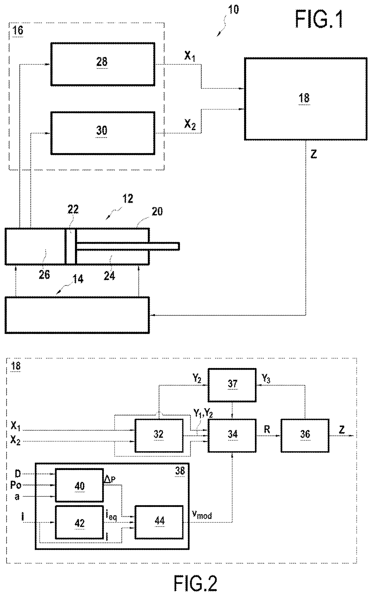
[0068]The invention relates to a method for controlling a cylinder as well as to a device for controlling a cylinder, making it possible to implement the method. This control method makes it possible to identify the most reliable position sensor from among a set of position sensors and to control the position of the cylinder piston using the piston position measurements supplied by this position sensor.

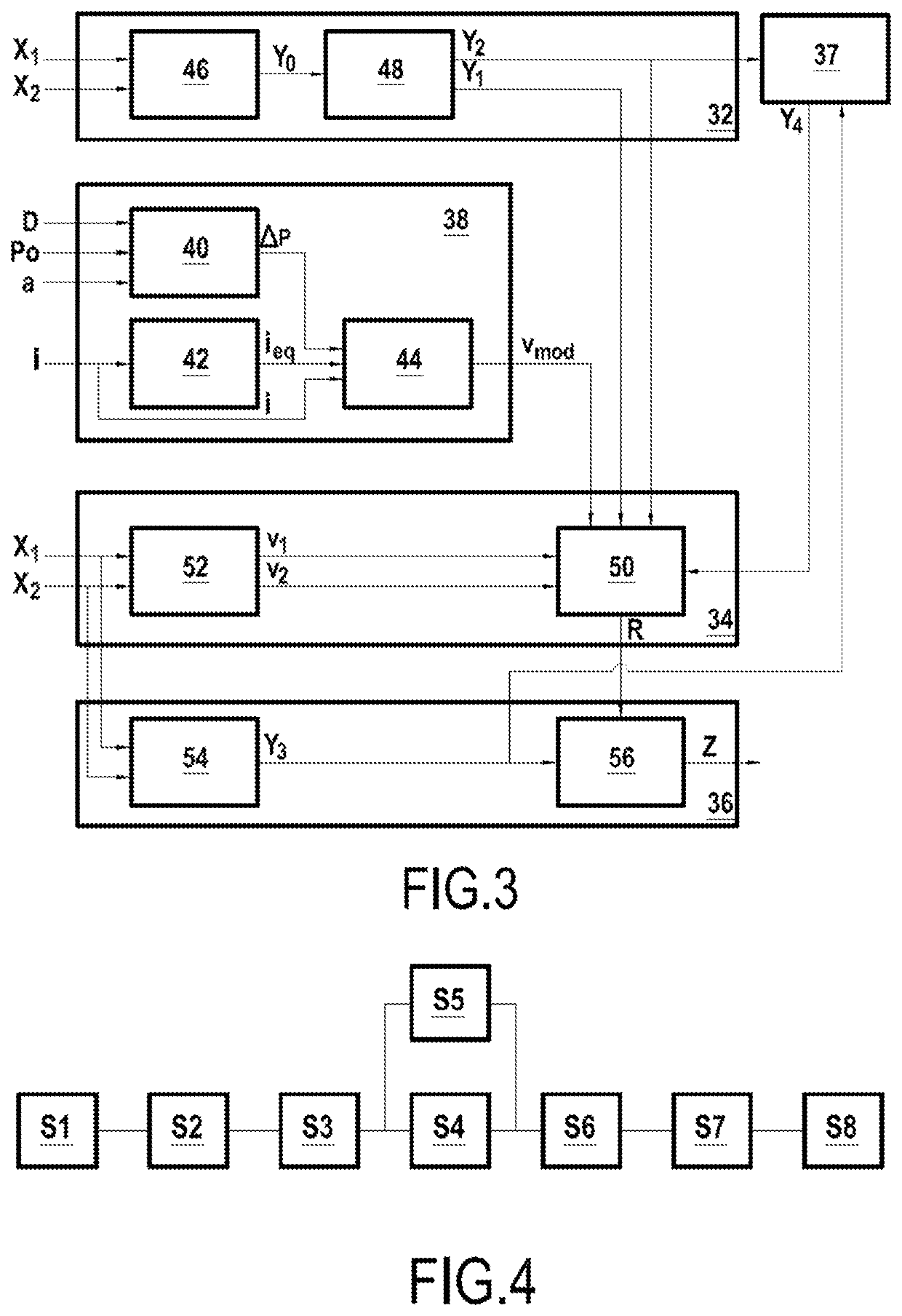
[0069]Using FIGS. 1 to 3, a device for controlling a cylinder will now be described, in accordance with the present invention, allowing the implementation of a method for controlling a cylinder according to the invention.

[0070]In this non-limiting example, the cylinder is used to actuate variable-shimming blades in a compressor, forming movable members of a turbomachine. The turbomachine conventionally comprises a combustion chamber.

[0071]FIG. 1 illustrates a device 10 for controlling a cylinder 12 in accordance with the present invention. The control device 10 comprises a servo valve...


PUM


Abstract

A method for controlling a cylinder includes providing a cylinder having a piston, a servo valve and a measuring device having at least one first position sensor and one second position sensor, measurements are taken of the position of the piston in the cylinder body simultaneously with the first position sensor and the second position sensor, at least one first displacement speed of the piston is determined on the basis of the piston position measurements obtained with the first position sensor, at least one second displacement speed of the piston is determined on the basis of the piston position measurements obtained with the second position sensor, and each of the first and second determined displacement speeds of the piston are compared with a modelled or predetermined displacement speed of the piston, in such a way as to identify the most reliable position sensor.

Description

TECHNICAL FIELD[0001]This invention relates to the field of the control of cylinders, and particularly cylinders used to actuate the movable members of a variable-geometry turbomachine.[0002]In the field of aeronautics, the turbomachines of aircraft comprise members called “variable-geometry” members. A variable geometry of a turbomachine such as a turbojet engine is a movable member, the position of which can be controlled to act on the flow of a fluid through the turbojet engine, for example on the gas stream in the primary flow path of a twin spool turbojet engine, in order to control the behavior of the turbojet engine. Variable geometries may for example be valves or movable blades, such as VBV (Variable Bleed Valve) or stator blading with variable shimming. The valves may also be valves for adjusting the flow rate of the air for cooling the turbine casings, in a system for adjusting the clearance at the tips of the turbine blades by heat-shrinking the casings, in order to opti...

Claims


Application Information

Patent Timeline
Patent Type & Authority Applications(United States)
IPC IPC(8): F15B19/00
CPCF15B19/005F15B19/007F15B2211/8757F15B2211/857F15B2211/6336
Inventor LE BRUN, CHRISTOPHE MARC ALEXANDREYING, CHARLESFERRER BELLOTI CARDIN, ALEXIS
Owner SN DETUDE & DE CONSTR DE MOTEURS DAVIATION S N E C M A
Learn More