
Structure deflection measurement apparatus

a technology of deflection measurement and measurement apparatus, which is applied in the direction of bridges, instruments, image enhancement, etc., can solve the problem of difficult to grasp the relation between

Pending Publication Date: 2022-02-17
NEC CORP
View PDF0 Cites 1 Cited by
  • Summary
  • Abstract
  • Description
  • Claims
  • Application Information

AI Technical Summary

Benefits of technology

The present invention provides a structure deflection measurement apparatus that solves the problem of difficulty in determining the relationship between the force applied to a structure and the flexural rigidity of the structure based on measured deflection. The apparatus includes a deflection acquiring unit to measure the amount of deflection in a target region on the structure caused by a vehicle, a vehicle position acquiring unit to determine the vehicle's position on the structure at the time of measurement, and a rigidity coefficient calculating unit to calculate the rigidity coefficient based on the measured deflection, the vehicle position, and a relation equation. This allows for easier interpretation of the force applied to the structure. The invention also includes a computer-readable recording medium to record a program for executing the described process.

Problems solved by technology

According to the techniques described in Patent Documents 1 and 2 above, the relation between a force applied to a structure by a vehicle weight and a deflection amount caused on the structure can be grasped, but it is difficult to grasp the relation between the magnitude of the force applied to the structure by the vehicle weight and the flexural rigidity of the structure.

Method used


Image

  • Structure deflection measurement apparatus
  • Structure deflection measurement apparatus
  • Structure deflection measurement apparatus

Examples


first example embodiment

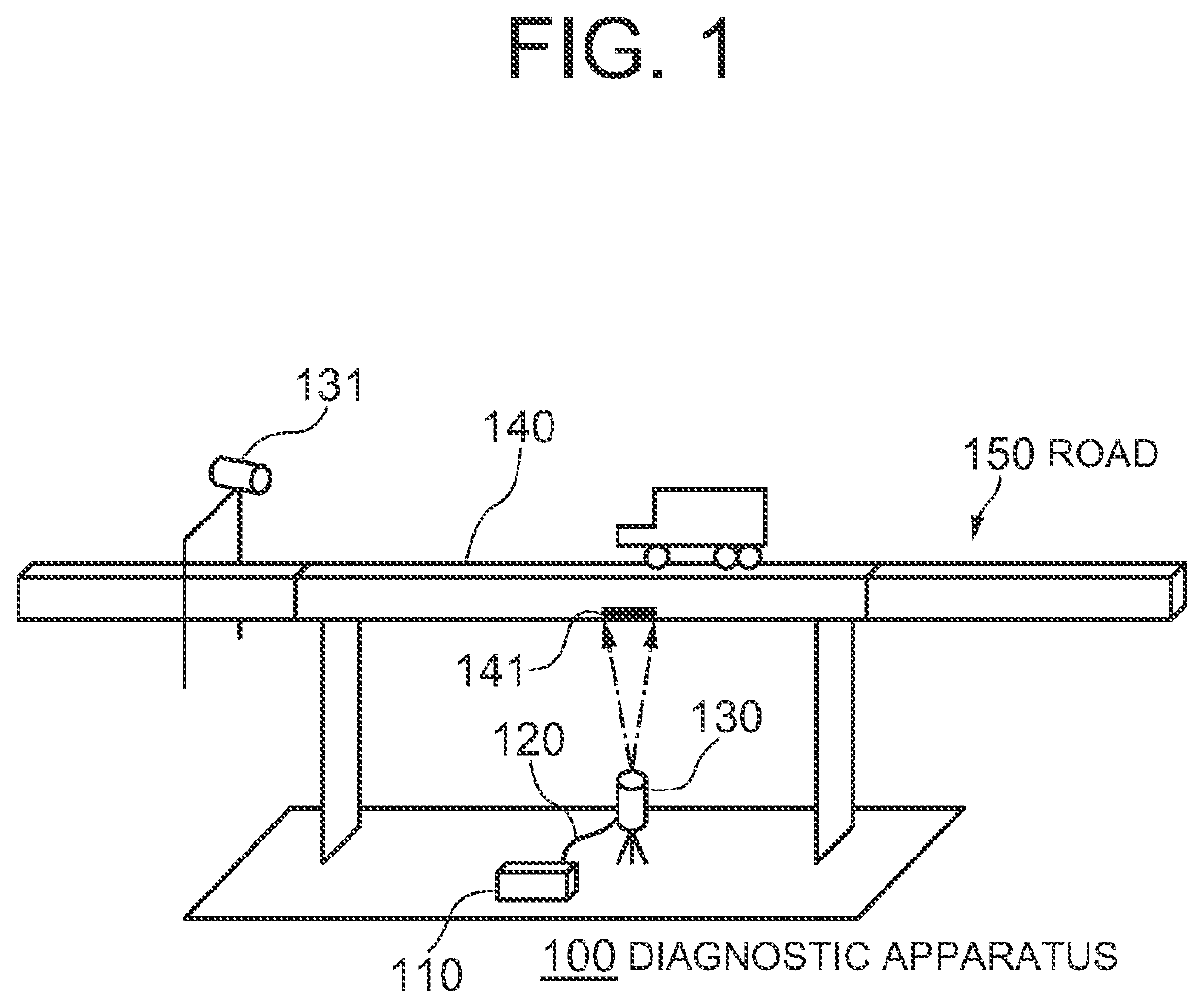
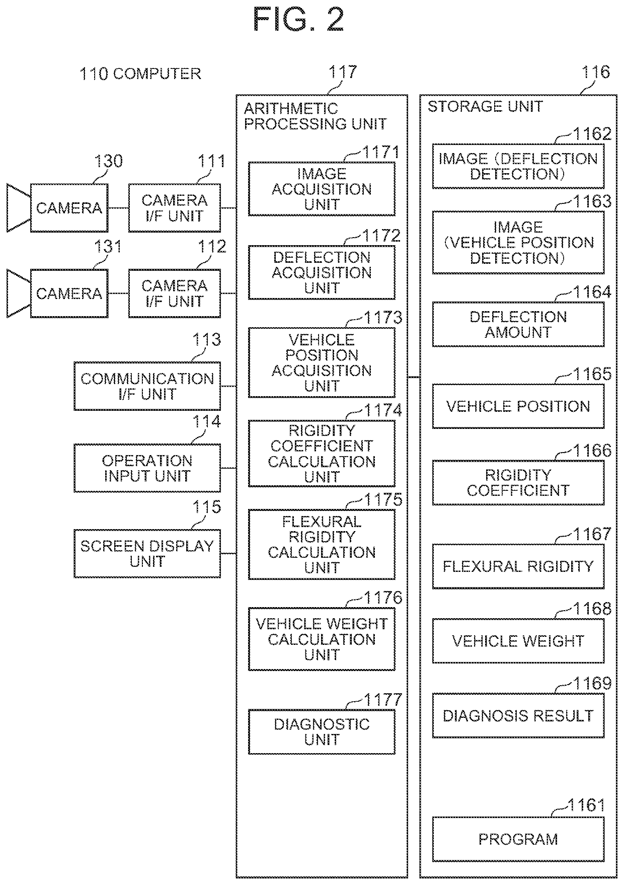
[0023]FIG. 1 is a view showing a configuration example of a deflection measurement apparatus 100 according to a first example embodiment of the present invention. Referring to FIG. 1, the deflection measurement apparatus 100 includes a computer 110 and two cameras 130 and 131.

[0024]The camera 130 is an image capture device for deflection detection that captures a region 141 existing on the surface of a structure 140 to be diagnosed at a given frame rate. In this example embodiment, the structure 140 is a bridge on which a road 150 such as an expressway crosses over a river or the like. In this example embodiment, the region 141 is part of a floor deck that is a diagnosis spot of the bridge. However, the structure 140 is not limited to a bridge. The structure 140 may be an elevated structure of an expressway or a railway, or the like. The size of the region 141 is, for example, several tens of centimeters square. The camera 130 is attached to a pan head (not shown) on a tripod (not s...

second example embodiment

[0074]Next, a second example embodiment of the present invention will be described with reference to FIG. 9. FIG. 9 is a block diagram of a structure deflection measurement apparatus 200 according to this example embodiment. In this example embodiment, the overview of a structure deflection measurement apparatus according to the present invention will be described.

[0075]Referring to FIG. 9, the structure deflection measurement apparatus 200 according to this example embodiment includes a deflection acquiring unit 201, a vehicle position acquiring unit 202, and a rigidity coefficient calculating unit 203.

[0076]The deflection acquiring unit 201 is configured to acquire a deflection amount caused at a predetermined position on a structure due to the weight of a vehicle traveling on the structure. The deflection acquiring unit 201 can be configured, for example, in the same manner as the deflection acquisition unit 1172 shown in FIG. 2, but is not limited thereto.

[0077]The vehicle posit...


PUM


Abstract

An apparatus includes: a deflection acquiring unit that acquires a deflection amount caused in a measurement target region on a structure by a vehicle traveling on the structure; a vehicle position acquiring unit that acquires a position of the vehicle on the structure at time when the deflection amount is acquired; and a rigidity coefficient calculating unit that calculates a rigidity coefficient specifying a relation between a magnitude of a force applied to the structure due to a weight of the vehicle and flexural rigidity of the structure, from a relation equation, the acquired deflection amount, and the detected position of the vehicle. The relation equation is established among a position of the vehicle on the structure, the magnitude of the force, a position of the measurement target region on the structure, a length of the structure, the flexural rigidity, and a deflection amount caused in the measurement target region.

Description

TECHNICAL FIELD[0001]The present invention relates to a structure deflection measurement apparatus, a structure deflection measurement method, and a recording medium.BACKGROUND ART[0002]When a vehicle passes a structure such as a bridge, a load is applied to the structure and the structure is displaced. Various techniques for measuring such structure displacement have been proposed.[0003]For example, Patent Document 1 describes a technique for measuring the deflection amount of a bridge when a given vehicle passes the bridge by using images captured by a video camera and a digital camera. To be specific, a characteristic of a vehicle traveling on a bridge is identified from a moving image captured by a video camera capturing the bridge, and a timing at which a given vehicle is passing the bridge is detected. Then, an image of the bridge is captured by a digital camera at the detected timing, and the distribution of the deflection amounts of the bridge is detected based on the captur...

Claims


Application Information

Patent Timeline
IPC IPC(8): G01M5/00G06T7/70G06K9/20G06T7/00
CPCG01M5/0008G06T7/70G06K9/2054E01D19/125G01M5/0041G06T2207/30236G06T2207/30184G06T7/0002E01D22/00G06V10/22
Inventor ISHII, ASUKA
Owner NEC CORP
Features
  • Generate Ideas
  • Intellectual Property
  • Life Sciences
  • Materials
  • Tech Scout
  • Unparalleled Data Quality
  • Higher Quality Content
  • 60% Fewer Hallucinations
Learn More