Centrifugal pump

a centrifugal pump and centrifugal technology, applied in specific fluid pumps, non-positive displacement pumps, fluid engines, etc., can solve the problems of fibrous substances easily getting hooked and agglomerating, wastewater pits or sumps will eventually overflow, and the frictional effect of fibrous substances can be reduced, so as to increase the pumping effect and reduce the frictional effect of fibrous substances

Active Publication Date: 2022-02-24
GRUNDFOS HLDG
View PDF0 Cites 0 Cited by
  • Summary
  • Abstract
  • Description
  • Claims
  • Application Information

AI Technical Summary

Benefits of technology

[0024]The cover gap may be designed large enough to reduce the frictional effects of fibrous substances squeezed between them and small enough to increase the pumping effect. Preferably, the cover gap may be in the range of 0.1 to 1 mm, preferably approximately 1 mm.
[0025]Optionally, the cover gap may be adjustable by adjusting the axial position of the impeller and / or the cover surface. This is beneficial to be able to trim the centrifugal pump to the desired needs and expected amounts and kind of fibrous substances in the pumped fluid.

Problems solved by technology

If the inflow of wastewater is larger than the outflow for a certain period of time, the wastewater pit or sump will eventually overflow.
That known solution has the disadvantage that the vane ridges act as leading edges on which in particular fibrous substances can easily get hooked and agglomerate.
If larger amounts of fibrous substances simultaneously hit the vane ridges, the scraper is not able to guide and transport them quickly enough into and through the grooves.
This results in pump clogging and a possible sump overflow.
It is thus a technical challenge to improve a centrifugal pump in such a way that the risk of pump clogging is reduced when larger amounts of fibrous substances hit the impeller simultaneously.
Such cutting for one reason is not desirable, because it would consume a considerable amount of power provided by a motor driving the impeller.

Method used


Image

  • Centrifugal pump
  • Centrifugal pump
  • Centrifugal pump

Examples


Embodiment Construction

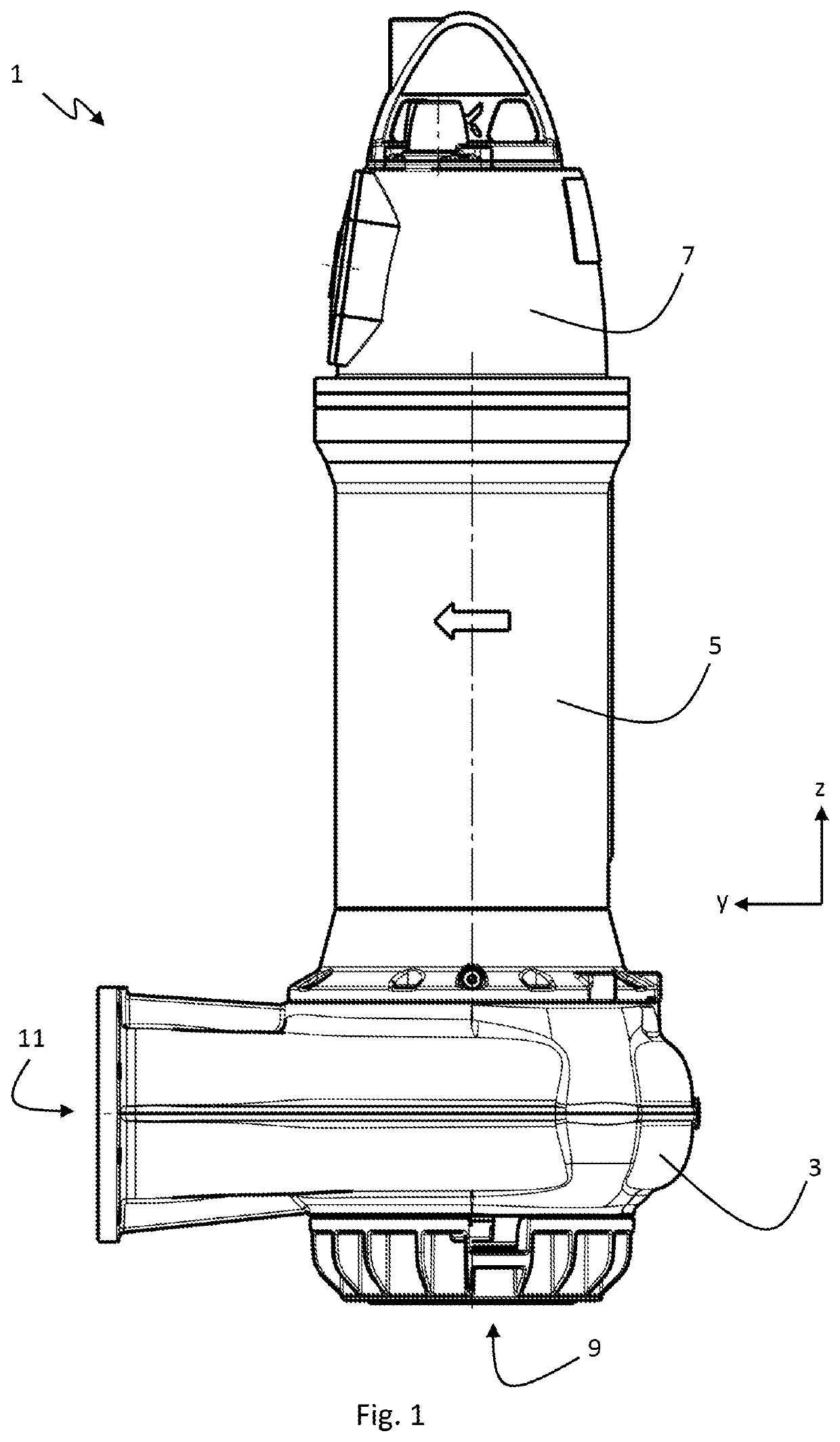
[0074]Referring to the drawings, FIG. 1 shows an elongate centrifugal pump 1 as a submersible wastewater pump that can be submersed into a wastewater pit or a duct to pump wastewater with fibrous substances. The pump 1 comprises a pump housing 3, a motor housing 5 and an electronics housing 7 arranged essentially along a vertical rotor axis R, wherein the motor housing 5 is arranged between the pump housing 3 and the electronics housing 7. The pump housing defines a fluid inlet 9 and a fluid outlet 11. The fluid inlet 9 is here a bottom opening in the pump housing 3, wherein the bottom opening is coaxial with the rotor axis R. It should be noted that the vertical pump setup shown herein is only a preferred setup. The rotor axis R may extend vertically or horizontally or in any other direction. For the sake of convenience, a right-handed Cartesian coordinate system is given in each figure, wherein the z-axis extends along the rotor axis R, i.e. here vertically upwards, the y-axis ext...


PUM


Abstract

A centrifugal pump (1) including: a pump housing (3) enclosing a pump chamber (13), the pump chamber (13) including a suction inlet (15) and a pressure outlet (17); an impeller (19) rotatably arranged within the pump chamber (13) for being driven to rotate about a rotor axis (R), the suction inlet (15) being located coaxial with the rotor axis (R); and at least one stationary scraper (39). The impeller (19) includes an impeller base (31) and at least one or more impeller vanes (33) extending from the impeller base (31) towards the suction inlet (15). Each of the impeller vanes (33) includes a radially innermost vane path (45) describing during impeller rotation a central volume (41) that is wider towards the suction inlet (15) than towards the impeller base (31) and configured to receive the at least one scraper (39) projecting from the suction inlet (15) into the central volume (41).

Description

CROSS REFERENCE TO RELATED APPLICATIONS[0001]This application is a United States National Phase Application of International Application PCT / EP2019 / 086375, filed Dec. 19, 2019, and claims the benefit of priority under 35 U.S.C. § 119 of European Application 18215565.5, filed Dec. 21, 2018, the entire contents of which are incorporated herein by reference.TECHNICAL FIELD[0002]The present invention pertains generally to centrifugal pumps, in particular to centrifugal pumps for pumping wastewater, sewage or other fluids containing solid, fibrous and / or viscous substances with a tendency to cause clogging in the centrifugal pump.TECHNICAL BACKGROUND[0003]Sewage or wastewater collection systems for wastewater treatment plants typically comprise one or more wastewater pits, wells or sumps for temporarily collecting and buffering wastewater. Typically, wastewater flows into such pits passively under gravity flow and / or actively driven through a force main. One, two or more pumps are usuall...

Claims


Application Information

Patent Timeline
Patent Type & Authority Applications(United States)
IPC IPC(8): F04D7/04F04D29/42F04D29/22
CPCF04D7/04F04D29/2294F04D29/42F04D7/045F04D29/2288F04D29/4293
Inventor CSÁNYI, RÓBERT
Owner GRUNDFOS HLDG
Why Eureka
Try Eureka