
Device and Method for Manufacturing Coated Welding Rod

a technology of coating welding rods and manufacturing methods, which is applied in the direction of manufacturing tools, welding/cutting media/materials, welding apparatus, etc., can solve the problems of affecting the service life of workpieces, affecting the effectiveness and reliability of welding joints, and polluting the environmen

Active Publication Date: 2022-03-03
ZHENGZHOU RES INST OF MECHANICAL ENG CO LTD
View PDF0 Cites 0 Cited by
  • Summary
  • Abstract
  • Description
  • Claims
  • Application Information

AI Technical Summary

Benefits of technology

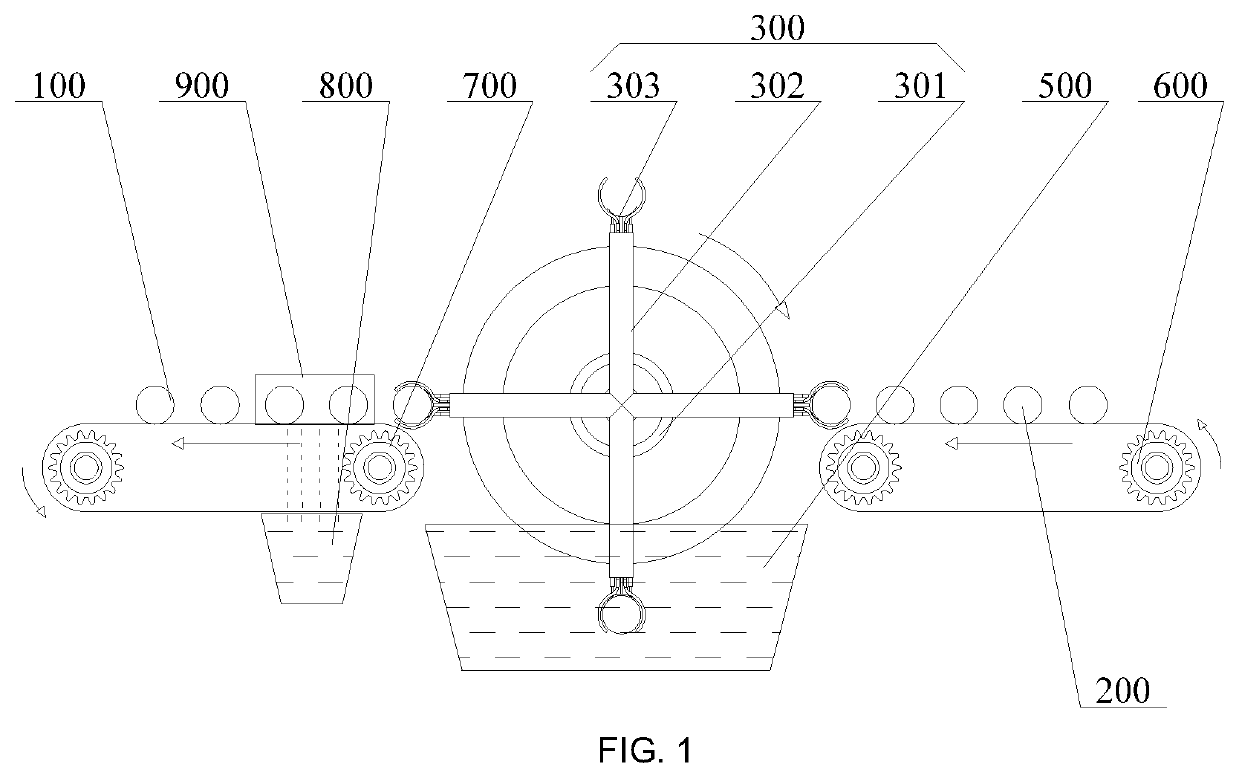
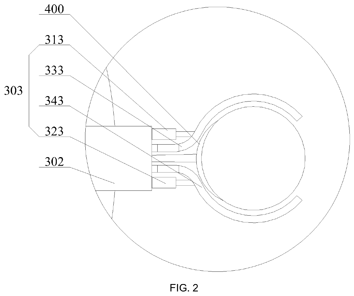
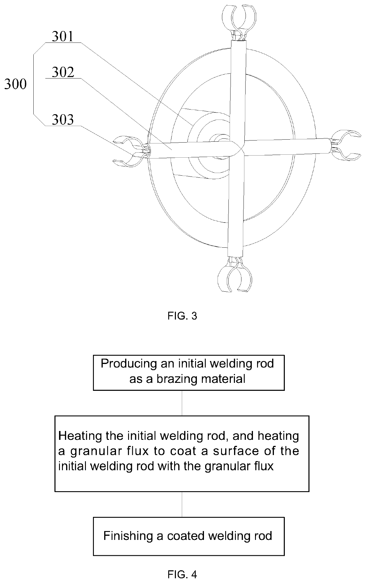
The present disclosure provides a device for manufacturing a coated welding rod by heating and coating the rod with a flux. The device includes a grabbing device for one-by-one grabbing of welding rods, a heating device at the grabbing end, and a flux storage device. The heated rod is then transported into the flux storage device, where the flux adheres to the rod surface. The process is done without using harmful organic binder, reducing pollution to the environment. The technical effects are cleaner welds, reduced pollution, and improved reliability and service life of welded joints.

Problems solved by technology

On the one hand, toxic and hazardous gases are released from the organic binders during the manufacture of and welding use with the coated brazing materials, which will pollute the environment and endanger the health of people.
On the other hand, the organic binders are not completely decomposed during welding so that some organic residues remain in the welded joints, which will cause welding defects and severely affect the effectiveness and reliability of the welded joints and the service life of workpieces.

Method used


Image

  • Device and Method for Manufacturing Coated Welding Rod
  • Device and Method for Manufacturing Coated Welding Rod
  • Device and Method for Manufacturing Coated Welding Rod

Examples


Embodiment Construction

[0069]In order to further clarify the objects, technical solutions, and advantages of the embodiments of the present disclosure, the technical solutions of the embodiments of the present disclosure will be described below clearly and completely with reference to the drawings of the embodiments of the present disclosure. It is apparent that the embodiments to be described are some, rather than all of the embodiments of the present disclosure. Generally, the components of the embodiments of the present disclosure, as described and illustrated in the figures herein, may be arranged and designed in a wide variety of different configurations.

[0070]Thus, the following detailed description of the embodiments of the present disclosure, as represented in the figures, is not intended to limit the scope of the present disclosure as claimed, but is merely representative of selected embodiments of the present disclosure. All the other embodiments obtained by those of ordinary skill in the art in...


PUM

PropertyMeasurementUnit
temperatureaaaaaaaaaa
lengthaaaaaaaaaa

Abstract

The present disclosure provides a device and method for manufacturing a coated welding rod. The device for manufacturing a coated welding rod includes a grabbing device, a heating device, and a flux storage device. The heating device is configured to heat a welding rod in the grabbing device. A flux in granular form is stored in the flux storage device, the grabbing device is configured to transport the heated welding rod into the flux storage device, and the heated welding rod is configured to heat the flux surrounding the welding rod into a viscous glassy state so that the flux in the viscous glassy state adheres to the surface of the welding rod. The heated welding rod enables the granular flux to be formed into a viscous glassy state so that the flux can be adhered directly to the surface of the welding rod.

Description

TECHNICAL FIELD[0001]The present disclosure relates to the technical field of manufacture of welding rods, and in particular to a device and method for manufacturing a coated welding rod.BACKGROUND ART[0002]Brazing materials are widely applied in fields such as aerospace, electrical machinery, automobiles, electronic information, and household refrigeration appliances and can be dubbed industrial “universal glue”. In the conventional production of coated brazing materials, it is necessary to add an organic binder to a flux to form a viscous paste, which is then applied (coated) to surfaces of welding rods as brazing materials. On the one hand, toxic and hazardous gases are released from the organic binders during the manufacture of and welding use with the coated brazing materials, which will pollute the environment and endanger the health of people. On the other hand, the organic binders are not completely decomposed during welding so that some organic residues remain in the welded...

Claims


Application Information

Patent Timeline
Patent Type & Authority Applications(United States)
IPC IPC(8): B23K35/40B23K35/365B23P15/00
CPCB23K35/404B23P15/00B23K35/365B23K35/406B05C3/09B05C9/14B05C11/1039B05C13/02
Inventor LONG, WEIMINZHONG, SUJUANDONG, HONGWEIZHANG, LEIPEI, YINYINZHANG, GUANZINGCHENG, YAFANGZHU, KUN
Owner ZHENGZHOU RES INST OF MECHANICAL ENG CO LTD
Learn More