
Method and screw spindle pump for delivering a gas/liquid mixture

Active Publication Date: 2022-03-03
LEISTRITZ PUMPEN
View PDF0 Cites 0 Cited by
  • Summary
  • Abstract
  • Description
  • Claims
  • Application Information

AI Technical Summary

Benefits of technology

The patent aims to enhance the efficiency of delivering gas / liquid mixtures, allowing for the simultaneous delivery of large liquid amounts.

Problems solved by technology

Although the optimization of the operating parameter for achieving the above-described properties for large gas proportions can lead to a slight drop in efficiency for large liquid proportions of the gas / liquid mixture, if sufficiently large gas proportions occur sufficiently frequently, a considerably energy saving is achieved since the power requirement for these periods of time is considerably below that of conventional screw spindle pumps.

Method used


Image

  • Method and screw spindle pump for delivering a gas/liquid mixture
  • Method and screw spindle pump for delivering a gas/liquid mixture
  • Method and screw spindle pump for delivering a gas/liquid mixture

Examples


Embodiment Construction

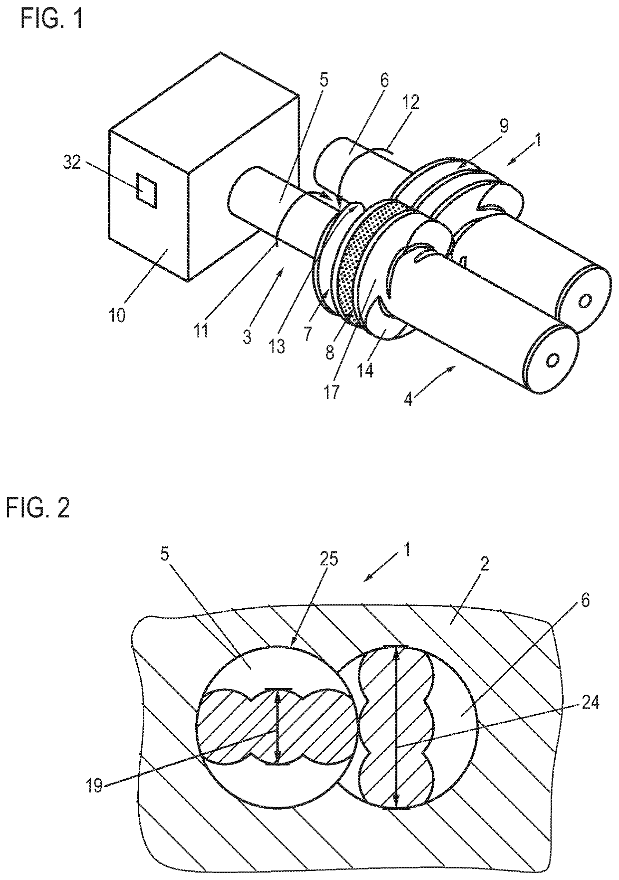
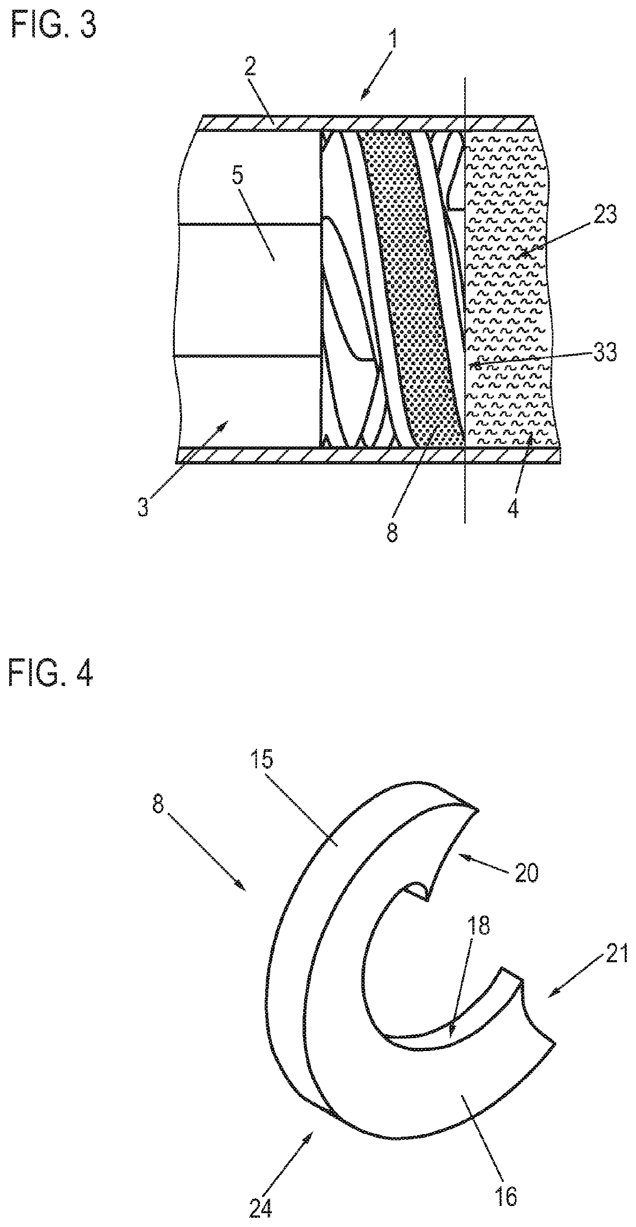
[0035]FIGS. 1, 2 and 3 show various detail views of a screw spindle pump which serves for delivery of a fluid that is a gas / liquid mixture. Here, FIG. 1 schematically shows a perspective view of the drive spindle 5 and the running spindle 6 of the screw spindle pump 1, wherein, for reasons of clarity, the housing 2 is not illustrated in FIG. 1. FIG. 1 illustrates in particular the shape of the screw profiles of the drive spindle 5 and the running spindle 6, and also the interengagement thereof.

[0036]FIG. 2 shows a face section, in which there can be seen in particular the interaction of the drive spindle 5 and the running spindle 6 with the housing 2 for forming multiple separate pump chambers 7, 8, 9, which are in turn indicated in FIG. 1 since they extend beyond the section plane shown in FIG. 2.

[0037]For illustrating the transport of fluid from a fluid inlet 3, formed by the housing 2, to a fluid outlet 4, formed by the housing 2, by way of operation of the drive spindle 5 and th...


PUM


Abstract

A method for delivering a gas / liquid mixture fluid via a screw spindle pump that has a housing forming at least one fluid inlet and one fluid outlet and in which a drive spindle and a running spindle, coupled in terms of rotation, are accommodated. The spindles, in each rotation position of the drive spindle, delimit together with the housing multiple pump chambers. The drive spindle is rotated by a drive in a drive direction, whereby a respective one of the pump chambers that is initially open toward the respective fluid inlet is closed off. The resulting closed-off pump chamber is moved axially toward the fluid outlet and, there, upon attainment of an opening rotation angle, is opened toward the fluid outlet. The drive spindle is driven so that, for a given pump geometry of the screw spindle pump, the pressure in the respective pump chamber prior to and / or upon attainment of the opening rotation angle is increased in relation to the suction pressure of the screw spindle pump, which prevails in the region of the respective fluid inlet, by at most 20% or by at most 10% of a difference in pressure between the suction pressure and the pressure in the region of the fluid outlet.

Description

CROSS-REFERENCE TO RELATED APPLICATIONS[0001]The present application claims priority of DE 10 2020 122 460.5, filed Aug. 27, 2020, the priority of this application is hereby claimed, and this application is incorporated herein by reference.BACKGROUND OF THE INVENTION[0002]The invention relates to a method for delivering a fluid which is a gas / liquid mixture by way of a screw spindle pump, said screw spindle pump having a housing which forms at least one fluid inlet and one fluid outlet and in which at least one drive spindle and at least one running spindle, coupled in terms of rotation to the latter, of the screw spindle pump are accommodated, which spindles, in each rotation position of the drive spindle, delimit together with the housing multiple pump chambers, wherein the drive spindle is rotated by a drive in a drive direction, whereby a respective one of the pump chambers that is initially open toward the respective fluid inlet is closed off, the resulting closed-off pump cham...

Claims


Application Information

Patent Timeline
IPC IPC(8): F04C2/16
CPCF04C2/16F04C2210/24F04C15/00F04C15/06F04C2/084F04C2250/20F04C2270/054F04C2270/052
Inventor MAURISCHAT, ROLAND
Owner LEISTRITZ PUMPEN
Learn More