Eureka AIR delivers breakthrough ideas for toughest innovation challenges, trusted by R&D personnel around the world.

Monitoring of the state of health of at least two vibration sensors of a bypass turbomachine

Pending Publication Date: 2022-03-03
SN DETUDE & DE CONSTR DE MOTEURS DAVIATION S N E C M A
View PDF0 Cites 0 Cited by
  • Summary
  • Abstract
  • Description
  • Claims
  • Application Information

AI Technical Summary

Benefits of technology

The patent describes a system that can detect and measure vibrations quickly and accurately, even in the event of a sensor failure. This system can also rehabilitate a failing sensor. The technical effect is to improve the reliability and efficiency of vibration detection and measurement.

Problems solved by technology

Such detection rationale however has limits, with false vibration sensor failures being wrongly declared.The monitoring phases are not optimal, the vibratory levels in these phases are often below the detection levels of a sensor breakdown:During operating at high temperature, since the speed of the turbomachine is higher than during operating at nominal temperature it can indicate that it is in a monitoring phase, and levels are not being registered during the provided phase, all the more so as they can also be below the detection levels of a sensor breakdown.

Method used


Image

  • Monitoring of the state of health of at least two vibration sensors of a bypass turbomachine
  • Monitoring of the state of health of at least two vibration sensors of a bypass turbomachine
  • Monitoring of the state of health of at least two vibration sensors of a bypass turbomachine

Examples


Embodiment Construction

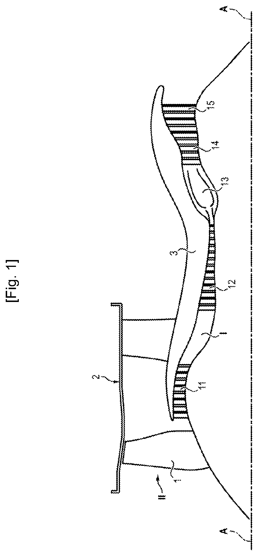
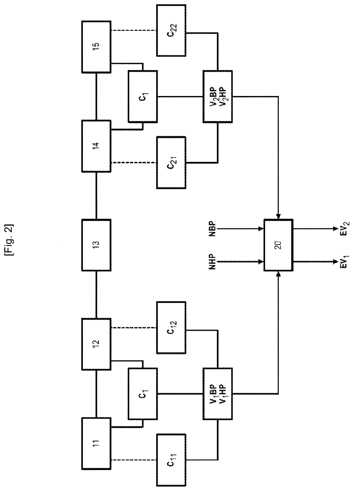
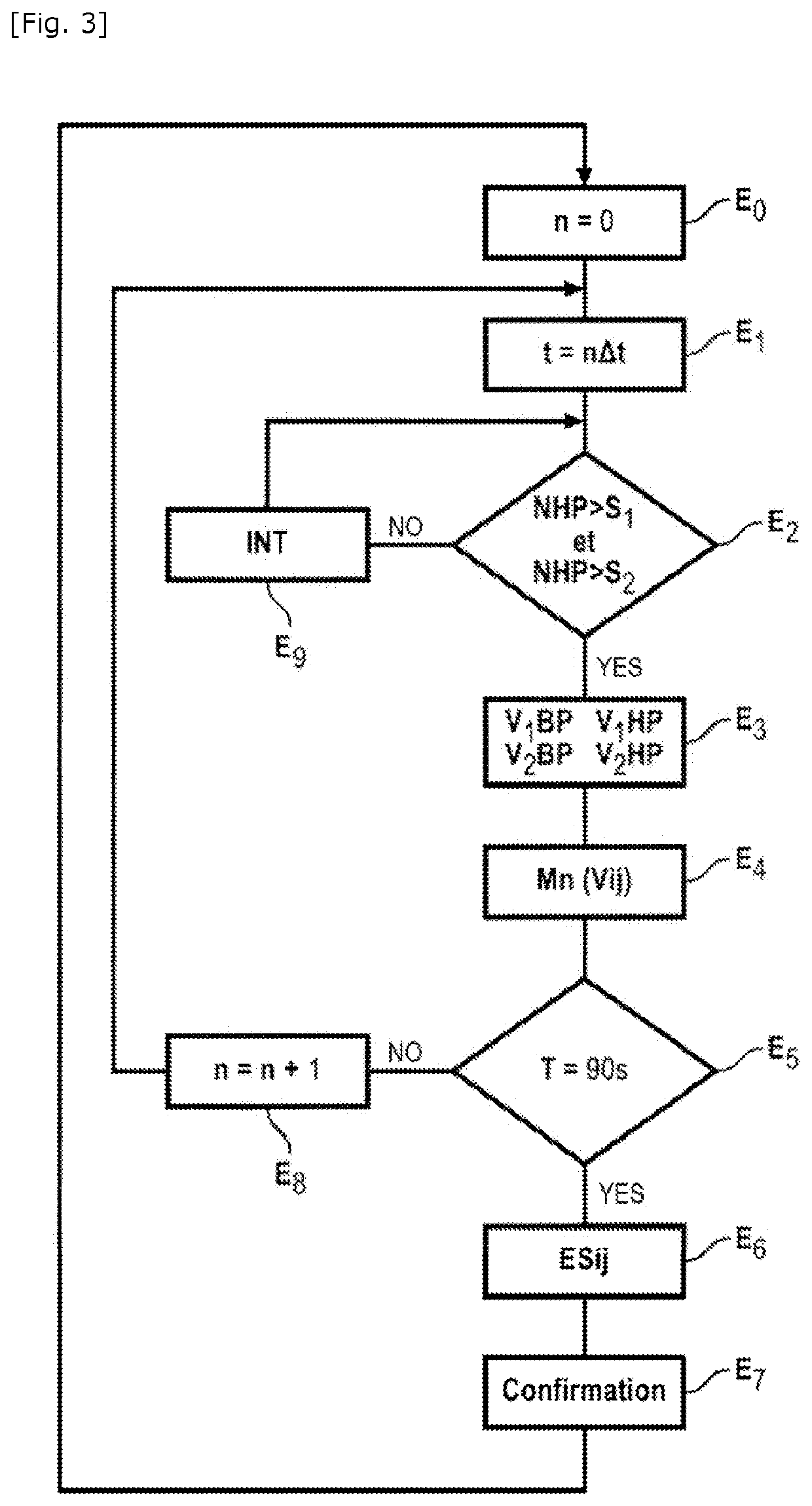
[0037]FIG. 1 shows a bypass turbomachine of an aircraft, comprising from upstream to downstream in the direction of gas flow (according to the engine axis AA) a ducted fan 1, a primary annular flow space I and a secondary annular flow space II (secondary duct) delimited by an external casing 2 and an internal hub 3. In the primary duct I the turbomachine comprises a low-pressure compressor 11, a high-pressure compressor 12, a combustion chamber 13, a 14 high-pressure turbine and a 15 low-pressure turbine.

[0038]The turbomachine therefore comprises a low-pressure body and a high-pressure body at the front and at the rear (in the direction of gas flow).

[0039]As mentioned at the outset vibration sensors are arranged at the front and at the rear to measure vibrations of the low-pressure and high-pressure bodies.

[0040]As illustrated schematically in FIG. 2, according to an embodiment a sensor C1 measures vibrations V1BP, V1HP of the low-pressure and high-pressure bodies at the front, and ...


PUM


Abstract

The invention relates to a monitoring process of the state of health of at least two vibration sensors of a twin turbomachine comprising a low-pressure body and a high-pressure body, a vibration sensor being located at the front of the turbomachine, a vibration sensor being located at the rear of the turbomachine, each of the sensors being configured to measure vibrations of the low-pressure and high-pressure bodies at the front and at the rear of the turbomachine, the process being executed in a processing unit (20) of the turbomachine communicating with each of the sensors and comprising the following steps:reception of the low-pressure (NBP) and high-pressure (NHP) speeds of the turbomachine and when said speeds are simultaneously in predetermined ranges,reception of the front and rear vibratory levels of the low- and high-pressure bodies registered by each sensor;determination of the average of the values of the vibratory levels of the low- and high-pressure bodies received over a predetermined reception period;determination of the state of health of said at least first and second vibration sensors from comparison of the average values of the vibratory levels of the low- and high-pressure bodies determined at predetermined thresholds.

Description

GENERAL TECHNICAL FIELD[0001]The invention relates to the monitoring of the state of health of a bypass turbomachine of an aircraft and more particularly by means of the monitoring of vibratory levels in the turbomachine. And the invention relates even more particularly to the monitoring of vibration sensors used for this purpose.PRIOR ART[0002]The state of health of a turbomachine is conventionally monitored by all kinds of sensors. Of these, vibration sensors are indispensable as they quickly detect when a part is broken, an increase in clearance and any other failure capable of endangering the turbomachine.[0003]In the direction of circulation of air flow a bypass turbomachine conventionally comprises a fan, a low-pressure compressor, a high-pressure compressor, a combustion chamber, a high-pressure turbine and a low-pressure turbine.[0004]A known solution for monitoring vibrations of the turbomachine is to arrange a vibratory sensor at the front of the turbomachine and another v...

Claims


Application Information

Patent Timeline
IPC IPC(8): G01H3/00F01D21/00
CPCG01H3/005F01D21/003F05D2220/323F05D2270/334F05D2260/83F05D2260/80F01D25/04G01H1/006F05D2260/96F01D17/02
Inventor ALEKSANDER, BORIS
Owner SN DETUDE & DE CONSTR DE MOTEURS DAVIATION S N E C M A
Why Eureka
Eureka Blog
Learn More