Inductor component

a technology of components and components, applied in the direction of transformer/inductance details, transformer/inductance coils/windings/connections, inductances, etc., can solve the problems of increasing dc electric resistance, limiting the length of linear or meandering inductor wires,

Pending Publication Date: 2022-03-03
MURATA MFG CO LTD
View PDF0 Cites 0 Cited by
  • Summary
  • Abstract
  • Description
  • Claims
  • Application Information

AI Technical Summary

Benefits of technology

[0004]For example, in an inductor component requiring a large current such as a power inductor, when DC electric resistance is prioritized over an inductance value, the inductor wire may have a linear shape or a meander shape. However, in the inductor component described in Japanese Patent Application Laid-Open No. 2020-053636, there is a limit in disposing linear or meander inductor wire to increase the wiring length while suppressing an increase in DC electric resistance.
[0007]According to each of the above configurations, the element body is correspondingly long in the first direction. Therefore, it is possible to ensure that the inductor region is long in the first direction. Therefore, the wiring length of the wiring body of the inductor wire can be sufficiently secured.

Problems solved by technology

However, in the inductor component described in Japanese Patent Application Laid-Open No. 2020-053636, there is a limit in disposing linear or meander inductor wire to increase the wiring length while suppressing an increase in DC electric resistance.

Method used


Image

  • Inductor component
  • Inductor component
  • Inductor component

Examples


first embodiment

[0038]Hereinafter, a first embodiment of an inductor component will be described. In the drawings, components may be illustrated in an enlarged manner for easy understanding. The dimension ratios of the components may be different from the actual ones or those in another figure.

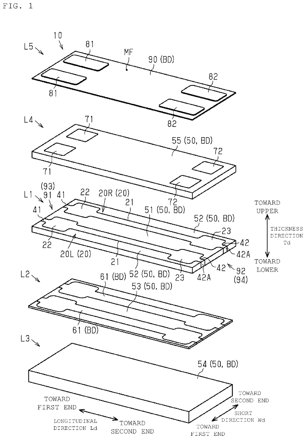
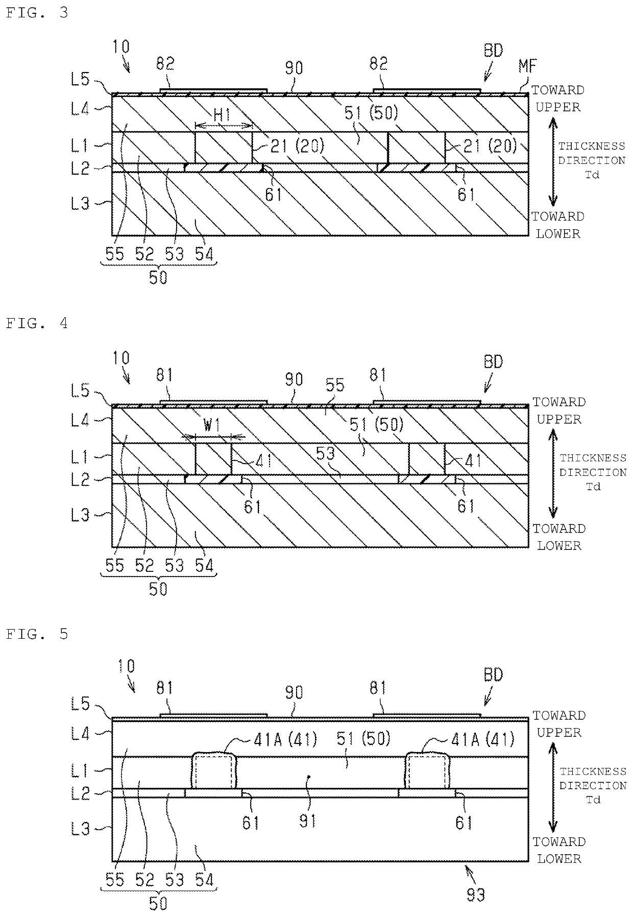
[0039]As illustrated in FIG. 1, an inductor component 10 has a structure in which five layers are laminated in a thickness direction Td as a whole. In the following description, one side in the thickness direction Td is an upper side, and the opposite side is a lower side.

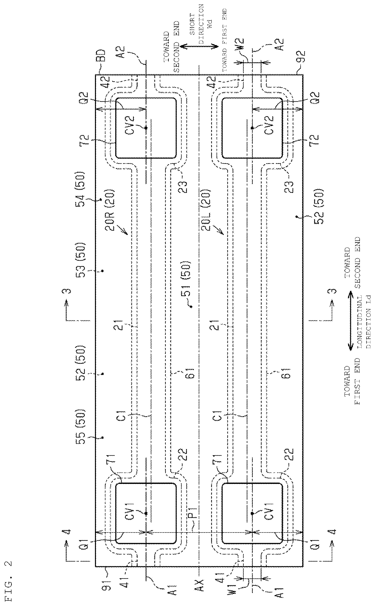
[0040]A first layer L1 includes two inductor wires 20, a first support wire 41 and a second support wire 42 extending from each of the inductor wires 20, an inner magnetic path portion 51, and an outer magnetic path portion 52. In the following description, when it is necessary to distinguish the two inductor wires 20, one inductor wire 20 is referred to as a first inductor wire 20R, and the other inductor wire 20 is referred to as a second ...

second embodiment

[0134]Hereinafter, the second embodiment of the inductor component will be described. In the drawings, components may be illustrated in an enlarged manner for easy understanding. The dimension ratios of the components may be different from the actual ones or those in another figure. In addition, the description of the same configuration as that of the first embodiment may be simplified or omitted.

[0135]As illustrated in FIG. 21, the inductor component 10 as a whole has a structure in which five layers are laminated in the thickness direction Td. In the following description, one side in the thickness direction Td is an upper side, and the opposite side is a lower side.

[0136]The first layer L1 includes the first inductor wire 20R, the second inductor wire 20L, the first support wire 41, the second support wire 42, the inner magnetic path portion 51, and the outer magnetic path portion 52.

[0137]The first layer L1 has a rectangular shape when viewed from the thickness direction Td. A d...


PUM

PropertyMeasurementUnit
thicknessaaaaaaaaaa
grain diameteraaaaaaaaaa
thicknessaaaaaaaaaa

Abstract

An inductor component includes a rectangular parallelepiped element body inside which a inductor wire extends in the first layer. The inductor wire includes a wiring body extending linearly, and first and second pads at first and second ends, respectively, of the wiring body. Of the surface of the element body, the dimension of the upper main face in the thickness direction in the longitudinal direction is 2.5 times or more the dimension of the main face in the short direction. When viewed from the thickness direction, the smallest rectangular region that is divided by a long side extending in the longitudinal direction and a short side extending in the short direction and that surrounds the whole wiring body is defined as an inductor region. The dimension of the first side of the inductor region is three times or more the dimension of the second side of the inductor region.

Description

CROSS-REFERENCE TO RELATED APPLICATION[0001]This application claims benefit of priority to Japanese Patent Application No. 2020-142765, filed Aug. 26, 2020, the entire content of which is incorporated herein by reference.BACKGROUNDTechnical Field[0002]The present disclosure relates to an inductor component.Background Art[0003]The inductor component described in Japanese Patent Application Laid-Open No. 2020-053636 includes an element body having a main face. In the element body, the inductor wire extends spirally in a direction along the main face. When viewed from a direction orthogonal to the main face, the element body has a quadrangular shape, and has a side extending in the longitudinal direction and a side extending in the width direction. The dimension in the longitudinal direction and the dimension in the width direction of the element body are substantially the same.SUMMARY[0004]For example, in an inductor component requiring a large current such as a power inductor, when D...

Claims


Application Information

Patent Timeline
Patent Type & Authority Applications(United States)
IPC IPC(8): H01F27/28H01F5/00
CPCH01F27/2804H01F5/003H01F17/0013H05K1/111H01F17/0006H01F2017/048H01F27/292
Inventor YOSHIOKA, YOSHIMASAKUDOU, RYO
Owner MURATA MFG CO LTD
Why Eureka
Try Eureka