Over-temperature alarm wiring device and system

A wiring device and terminal technology, which is applied in the direction of thermal switch components, etc., can solve the problems of not being able to monitor the contact temperature in real time, time-consuming and labor-intensive real-time performance, and low work efficiency, so as to achieve convenient over-temperature alarm, reduce workload, and low cost Effect

Inactive Publication Date: 2018-07-20
CHENGWU POWER SUPPLY CO STATE GRID SHANDONG ELECTRIC POWER CO LTD +1
View PDF6 Cites 0 Cited by
  • Summary
  • Abstract
  • Description
  • Claims
  • Application Information

AI Technical Summary

Problems solved by technology

However, using infrared temperature measurement and thermal imaging temperature measurement technology to measure temperature requires operation and maintenance personnel to go to the line and equipment site to measure the equipment and line contacts one by one. The labor intensity is high, the work efficiency is low, and the temperature of the contacts cannot be monitored in real time.
[0004] In view of the time-consuming and labor-intensive and poor real-time performance of the above-mentioned line contact temperature measurement method, no effective solution has been proposed

Method used


Image

  • Over-temperature alarm wiring device and system
  • Over-temperature alarm wiring device and system
  • Over-temperature alarm wiring device and system

Examples


Embodiment 1

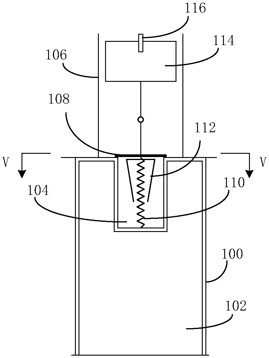
[0034] see figure 1 A structural schematic diagram of an over-temperature alarm wiring device shown; the device includes a wiring unit and an alarm unit; wherein the wiring unit includes a first insulating sleeve 100 and a connecting cylinder 102 matching the inner diameter of the first insulating sleeve 100 ; The terminal cylinder 102 is provided with a spiral groove ( figure 1 not shown in ); the spiral groove is used to accommodate the terminal; the center of the top of the above-mentioned terminal is provided with a cylindrical concave cavity with an inner diameter smaller than the inner diameter of the terminal;

[0035]The above-mentioned alarm unit includes a temperature-sensing chamber 104, an alarm component fixed at the center of the bottom of the temperature-sensing chamber, and a second insulating sleeve 106 outside the alarm component; the inner diameter of the above-mentioned temperature-sensing chamber 104 matches the inner diameter of the cylindrical recessed c...

Embodiment 2

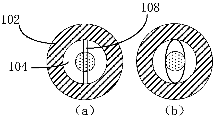
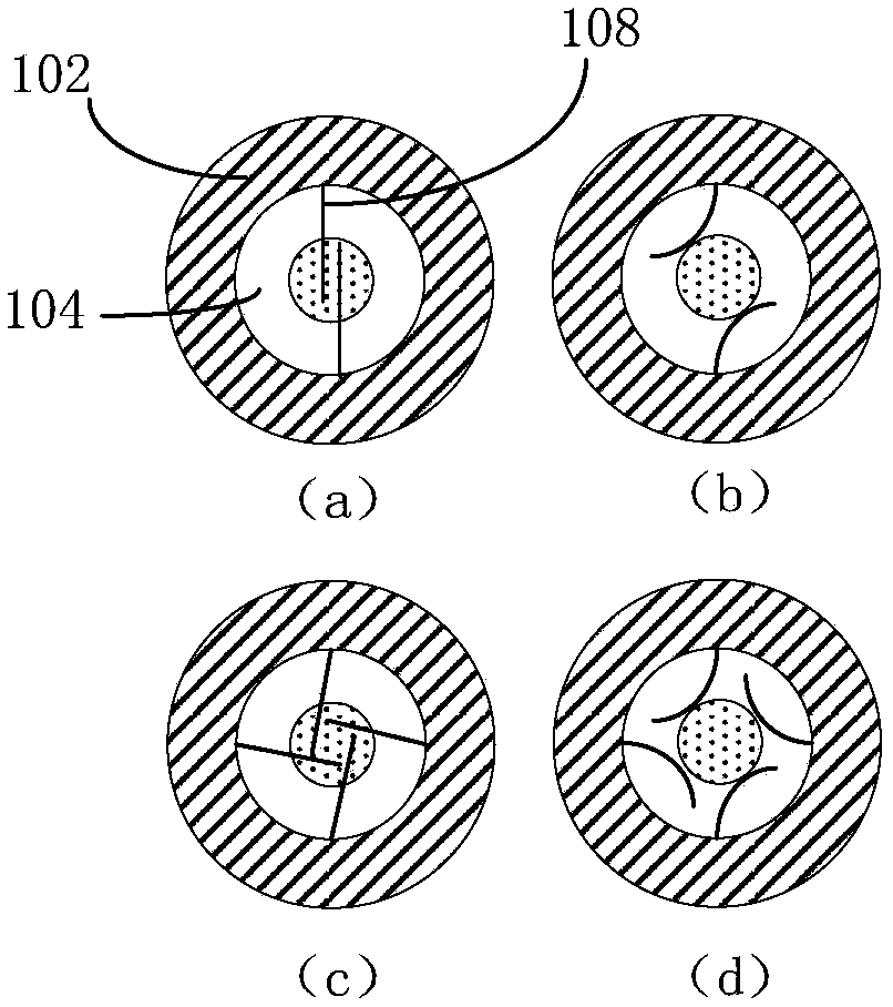
[0040] For a detailed description of the over-temperature alarm wiring device provided in the first embodiment, refer to figure 2 shown figure 1 The first sectional view along the V-V line; figure 2 A first arrangement of multiple temperature-sensitive metal sheets is shown, wherein the number of multiple temperature-sensitive metal sheets 108 is two; both ends of the temperature-sensitive metal sheets 108 are fixed to the edge of the opening of the temperature-sensing cavity 104 position; the positions of both ends of the temperature-sensitive metal sheet 108 are opposite to the temperature-sensing chamber; specifically, the length of the two temperature-sensitive metal sheets 108 can be the same as the diameter of the temperature-sensing chamber, so that the two temperature-sensitive metal sheets can be In the case of deformation, it is just fixed at the diameter of the opening of the temperature sensing chamber.

[0041] The above two temperature-sensitive metal sheets ...

Embodiment 3

[0056] see Figure 8 Shown is a schematic structural diagram of an over-temperature alarm wiring system; the system includes the above-mentioned over-temperature alarm wiring device 800 , a power line terminal 802 , and a substation or power distribution device 804 .


PUM


Abstract

The invention provides an overtemperature alarm wiring apparatus and system. The apparatus comprises a wiring unit and an alarm unit. When the temperature of a wiring end accommodated in a spiral groove of a wiring cylinder does not exceed a preset threshold, temperature-sensitive metal pieces arranged at an opening of a temperature-sensitive chamber clamp a bucking apparatus at the top portion of a driving spring inside the temperature-sensitive chamber, and the driving spring is at a compressed state; when the temperature of the wiring end exceeds the preset threshold, the wiring cylinder transfers the temperature to the multiple temperature-sensitive metal pieces arranged at the opening of the temperature-sensitive chamber, the temperature-sensitive metal pieces are deformed, and the diameters of the internal spaces of the multiple temperature-sensitive metal pieces are greater than the diameter of the top portion of the clamping apparatus; the driving spring moves; and an alarm direction board connected with the driving spring through the buckling apparatus extends outwards from a second insulation sleeve. According to the invention, overtemperature alarm can be conveniently performed on line contacts, the workload of operation personnel is reduced, time is saved, labor is saved, and the cost is low.

Description

technical field [0001] The invention relates to the field of on-line temperature measurement of power transmission and distribution lines and power transformation equipment, in particular to an over-temperature alarm wiring device and system. Background technique [0002] With the rapid development of the economy, electricity has become an inseparable source of energy for thousands of households, resulting in a substantial increase in total electricity consumption. During peak power consumption, power transmission and distribution lines and substation equipment will run at full load or even short-term overload, which will lead to overheating of equipment and connection points of wires, which will easily cause line burnout and large-scale power outages. [0003] In order to ensure the safe operation of the power grid, power line and equipment operation and maintenance personnel currently mainly use regular patrol lines and equipment, and use infrared measurement and thermal i...

Claims


Application Information

Patent Timeline
Patent Type & Authority Patents(China)
IPC IPC(8): H01H37/52H01H37/08
CPCH01H37/08H01H37/52
Inventor 牛广领牛德成李冀天刘娜张法忠马永波李丕燕袁存兵盛守才王瑞兰孙久仓聂永振
Owner CHENGWU POWER SUPPLY CO STATE GRID SHANDONG ELECTRIC POWER CO LTD
Why Eureka
Try Eureka