Flush water tank apparatus and flush toilet apparatus provided with the same

a technology of water tank and flushing toilet, which is applied in the direction of water installation, flushing device, construction, etc., can solve the problems of insufficient pressure in the cylinder, time-consuming, and insufficient time to discharge the water in the cylinder, and achieves the effect of quick water discharge, simple mechanism and short tim

Pending Publication Date: 2022-03-10
TOTO LTD
View PDF0 Cites 2 Cited by
  • Summary
  • Abstract
  • Description
  • Claims
  • Application Information

AI Technical Summary

Benefits of technology

[0047]According to the present invention, there can be provided a flush water tank apparatus capable of quickly discharging water in a discharge valve hydraulic drive portion with a simple mechanism while opening a discharge valve using a water supply pressure and returning to a state where a next toilet flush operation can be started in a short time, and a flush toilet apparatus provided with the same.

Problems solved by technology

However, the water supplied to the hydraulic cylinder device flows out through the drain portion, and flows into the low tank.
However, in the low tank apparatus disclosed in Japanese Patent Laid-Open No. 2009-257061, since it takes a long time to return the piston of the hydraulic cylinder device to an original position, the time is required until a next toilet flush operation can be started after one toilet flush operation.
Since the gap between the rod portion and the through hole is narrow, it takes a relatively long time to discharge the water in the cylinder.
In addition, when the gap is increased, the pressure in the cylinder is not sufficiently increased, which makes it difficult to push up the piston during the toilet flush operation.
Therefore, the gap cannot be simply increased.
However, in the low tank apparatus of this type, it is necessary to provide a dedicated electromagnetic valve for discharging the water in the cylinder, and therefore the structure of the apparatus is complicated and the hydraulic cylinder device is increased in size.

Method used


Image

  • Flush water tank apparatus and flush toilet apparatus provided with the same
  • Flush water tank apparatus and flush toilet apparatus provided with the same
  • Flush water tank apparatus and flush toilet apparatus provided with the same

Examples


first embodiment

[0140]Next, the operation of the flush water tank apparatus 4 according to the present invention and the flush toilet apparatus 1 provided with the same will be described.

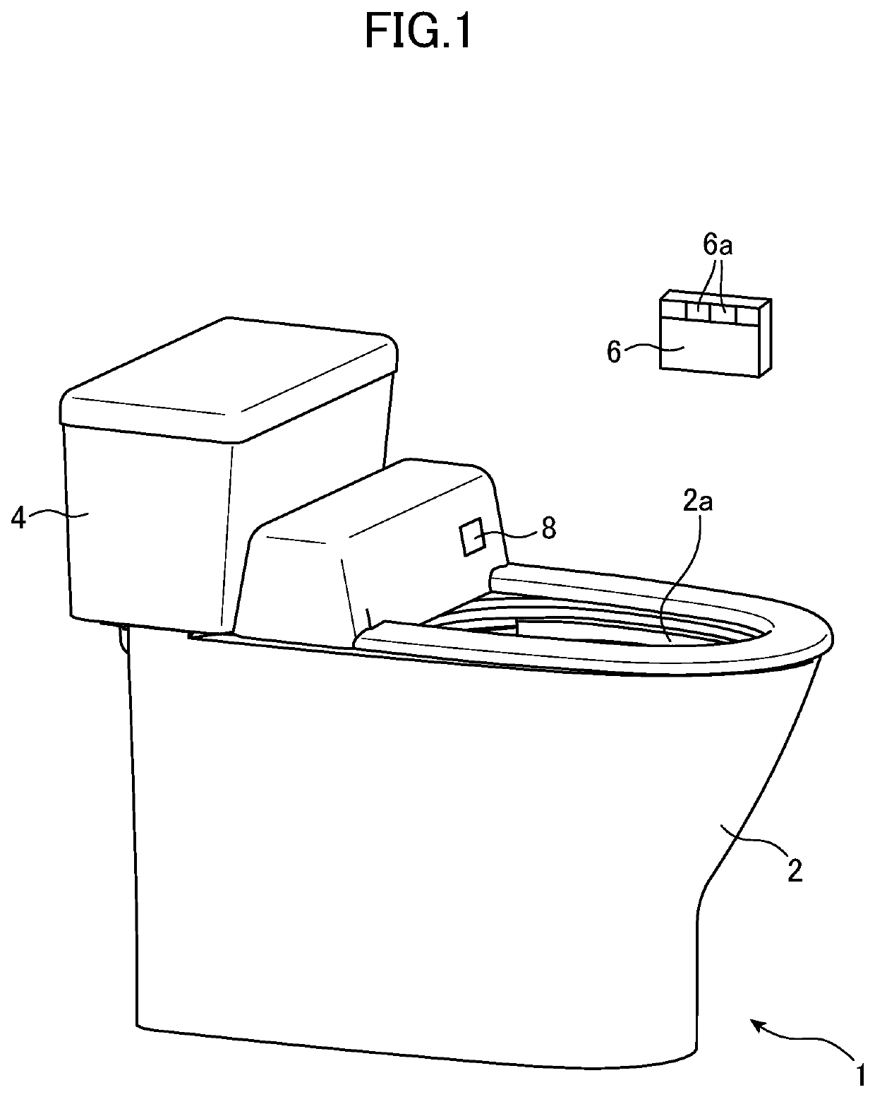
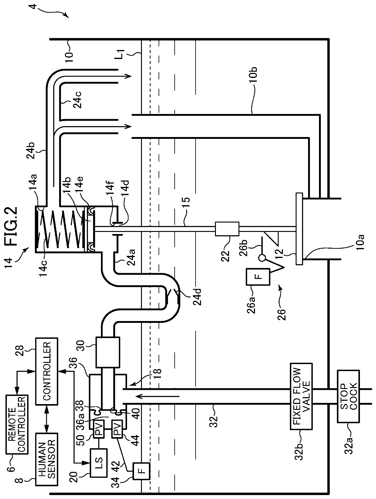
[0141]First, in the toilet flush standby state, the water level in the reservoir tank 10 is the predetermined water level L1, and the energization of the electromagnetic valve 20 is not performed. In this state, both of the electromagnetic valve-side pilot valve 50 and the float-side pilot valve 44 of the water supply controller 18 (FIG. 2) are in the closed state, and the valve seat 40 is closed by the main valve body 38. Next, when the user presses a flush button in the remote controller 6 (FIG. 1), the remote controller 6 transmits a command signal for flushing the toilet to the controller 28 (FIG. 2). In the flush toilet apparatus 1 of the present embodiment, after an elapse of a predetermined time period after a user's separation from the seat is detected by the human sensor 8 (FIG. 1), the command signal for ...

second embodiment

[0188]Next, referring to FIGS. 15 to 17, a flush water tank apparatus according to the present invention and a flush toilet apparatus provided with the same will be described.

[0189]The flush water tank apparatus of the present embodiment is different from the flush water tank apparatus in the first embodiment in the structure of the discharge / vacuum break valve device, and the other structures are the same as those in the first embodiment. Accordingly, the following describes only the points that are different between the first embodiment and the second embodiment of the present invention. Similar components, operations and effects are not described.

[0190]FIG. 15 is a perspective view of a discharge / vacuum break valve device provided in the flush water tank apparatus according to the second embodiment of the present invention. FIG. 16 is a cross-sectional view of the discharge / vacuum break valve device in a state where water is not supplied from a water supply controller. FIG. 17 is...

third embodiment

[0213]Next, referring to FIGS. 18 to 21, a flush water tank apparatus according to the present invention and a flush toilet apparatus provided with the same will be described.

[0214]The flush water tank apparatus of the present embodiment is different from the flush water tank apparatus in the first embodiment in the structure of the discharge / vacuum break valve device, and the other structures are the same as those in the first embodiment. Accordingly, the following describes only the points that are different between the first embodiment and the third embodiment of the present invention. Similar components, operations and effects are not described.

[0215]FIG. 18 is a perspective view of a discharge / vacuum break valve device provided in the flush water tank apparatus according to the third embodiment of the present invention. FIG. 19 is a perspective view illustrating the discharge / vacuum break valve device in which a case is partially cut away, and illustrates a state where the wate...


PUM


Abstract

There is provided a flush water tank apparatus capable of returning to a state where next toilet flush operation can be started in a short time while opening a discharge valve using a water supply pressure. A flush water tank apparatus (4) includes a reservoir tank (10), a discharge valve (12), a discharge valve hydraulic drive portion (14) configured to drive the discharge valve using a water supply pressure, and a discharge/vacuum break valve device (30) provided on an upstream side of the discharge valve hydraulic drive portion and configured to supply the water supplied from the upstream side to the discharge valve hydraulic drive portion on a downstream side. The discharge valve hydraulic drive portion includes a cylinder (14a) into which the water from the discharge/vacuum break valve device flows, and a piston (14b) configured to be moved by a pressure of the water flowing into the cylinder to move the discharge valve. The discharge/vacuum break valve device includes a valve body that operates to discharge the water flowing backward from the discharge valve hydraulic drive portion while opening the upstream side to an atmosphere when the supply of the water from the upstream side is stopped.

Description

BACKGROUND OF THE INVENTIONField of the Invention[0001]The present invention relates to a flush water tank apparatus, and particularly to a flush water tank apparatus configured to supply flush water to a flush toilet and a flush toilet apparatus provided with the same.Description of the Related Art[0002]Japanese Patent Laid-Open No. 2009-257061 discloses a low tank apparatus. In the low tank apparatus, a hydraulic cylinder device having a piston and a drain portion is arranged in a low tank provided with a discharge valve, and the piston and the discharge valve are connected to each other by a connection portion. To discharge flush water in the low tank, an electromagnetic valve is opened to thereby supply the water to the hydraulic cylinder device, so that the piston is pushed up. Since the piston is connected to the discharge valve by the connection portion, the movement of the piston causes the discharge valve to be pulled up to open the discharge valve, whereby the flush water ...

Claims


Application Information

Patent Timeline
Patent Type & Authority Applications(United States)
IPC IPC(8): E03D3/04E03D1/26E03D1/34E03D5/02
CPCE03D3/04E03D1/266E03D1/33E03D5/024E03D1/34E03D1/30E03D1/302E03D5/105
Inventor SHIMUTA, AKIHIROKITAURA, HIDEKAZUHAYASHI, NOBUHIROKUROISHI, MASAHIROHASHIMOTO, HIROSHISHINOHARA, KOKIHATAMA, KENJIYOSHIOKA, TAKASHI
Owner TOTO LTD
Why Eureka
Try Eureka