Gear pump

a gear pump and gear technology, applied in the direction of pump components, machines/engines, liquid fuel engines, etc., can solve the problems of unintentional failure, and reducing the efficiency of the gear pump

Pending Publication Date: 2022-03-10
IHI CORP
View PDF2 Cites 0 Cited by
  • Summary
  • Abstract
  • Description
  • Claims
  • Application Information

AI Technical Summary

Benefits of technology

[0009]As pressure on the sealing face extracted through the communication path contains a pressure variate of an opposite phase relative to fluctuation of pressurization applied to the bearing and acts as negative feedback to the third receiver face, the pressurization on the bearing is kept within a proper range.

Problems solved by technology

The pressurization on the bearing is required to be sufficient to counter this force and otherwise the bearing will float out of the gear wheel and then the fluid will begin to leak, thereby reducing the efficiency of the gear pump.
This would also cause reduction of efficiency of the gear pump and as well heat generation by the resistance might give rise to unintentional failure.
If the generated pressure is used to apply pressurization onto the bearing, increase in pressure on one face of the bearing leads to increase in pressure on the other face.
The present inventor, however, found out through his study that, when rotational speeds of the gears are increased in order to improve efficiency, the floating bearing could get unstable.

Method used


Image

  • Gear pump
  • Gear pump
  • Gear pump

Examples


Embodiment Construction

[0015]Exemplary embodiments will be described hereinafter with reference to the appended drawings.

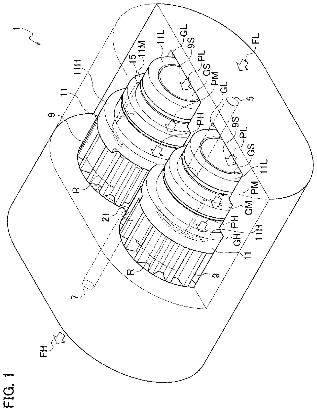
[0016]A gear pump according to the present embodiment is used for fuel supply to an aeronautic engine for example and it pressurizes and expels relatively low viscosity fluid like oil such as kerosene. The following description relates to an example which employs a pair of gears mutually in mesh to rotate in inverse directions but it is merely for convenience of explanation. Three or more gears may be used or use of only one gear is possible. Further, one of the gears is connected via a shaft or gearing with an external power source and the other is a follower gear, although any particular references will not be found in the following description. Or, both the gears may be driving gears.

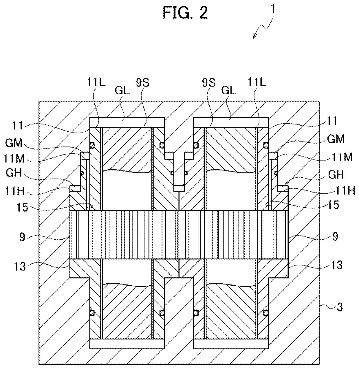
[0017]Referring mainly to FIGS. 1, 2, the gear pump 1 is generally constituted of a pair of gears mutually in mesh and a casing 3 housing them.

[0018]The casing 3 is provided with a suction port 5 and a d...


PUM


Abstract

A gear pump is provided with: a casing including a suction port configured to suck fluid, and a discharge port configured to expel the pressurized fluid; a gear including a wheel portion with gear teeth and an axially elongated shaft portion, the gear being so housed in the casing as to transport the fluid from the suction port to the discharge port; and a floating bearing rotatably supporting the shaft portion and being movable axially, the floating bearing including a sealing face in contact with the wheel portion, a receiver face axially opposed to the sealing face; and a communication path having an opening on the sealing face and communicating the opening with a third pressurization chamber defined by a third receiver face of the receiver face and the casing.

Description

CROSS-REFERENCE TO RELATED APPLICATIONS[0001]This application is a Continuation Application of PCT International Application No. PCT / JP2020 / 035162 (filed Sep. 17, 2020), which is in turn based upon and claims the benefit of priority from Japanese Patent Application No. 2019-182915 (filed Oct. 3, 2019), the entire contents of which are incorporated herein by reference.BACKGROUNDTechnical Field[0002]The disclosure herein relates to a gear pump of a floating bearing type, which uses rotation of gears to pressurize and expel fluid, and in particular to a gear pump that keeps applying proper pressure onto the floating bearings even at higher rotational speed.Description of the Related Art[0003]A gear pump is usually provided with a pair of gears mutually in mesh and a housing that houses the gears and, by rotating the pair of gears in a flow path defined by the housing, pressurizes and expels fluid. Although a large flow rate is unhopeful, it is preferably applicable to some uses in whic...

Claims


Application Information

Patent Timeline
Patent Type & Authority Applications(United States)
IPC IPC(8): F04C2/18F04C15/00
CPCF04C2/18F04C2240/60F04C2240/30F04C15/00F04C15/0042F04C2240/56F04C2240/54F04C2/088
Inventor TAKAMIYA, KENJI
Owner IHI CORP
Why Eureka
Try Eureka