Ball screw device and steering device

a technology of ball screw and steering device, which is applied in the direction of bearing unit rigid support, bearing, transportation and packaging, etc., can solve the problems of finding mounting error of holding members, and achieve the effect of reducing gear striking noise, preventing steering feeling of drivers, and easy manufacturing

Inactive Publication Date: 2020-10-22
JTEKT CORP
View PDF0 Cites 0 Cited by
  • Summary
  • Abstract
  • Description
  • Claims
  • Application Information

AI Technical Summary

Benefits of technology

The present disclosure provides a steering device and a ball screw device that can improve manufacturing efficiency without using a structure in which elastic members are interposed in a spigot portion, and use a force at the time of mounting a housing to prevent an influence of a processing error and accurately pressurize the elastic members. Additionally, the present disclosure provides a steering device and a ball screw device that can improve manufacturing efficiency of a housing without using a structure in which biasing members are interposed in a spigot portion, and can easily find a mounting error of holding members. This results in a housing structure that can be easily manufactured, a gear striking noise can be reduced, and a steering feeling of a driver can be prevented from lowering at the start of turning a steering wheel. Furthermore, this results in a housing structure that can be easily manufactured, and a mounting error of the holding members can be easily found.

Problems solved by technology

Further, the present disclosure provides a steering device and a ball screw device that can improve manufacturing efficiency of a housing without using a structure in which biasing members are interposed in a spigot portion, and can easily find a mounting error of holding members.

Method used


Image

  • Ball screw device and steering device
  • Ball screw device and steering device
  • Ball screw device and steering device

Examples


Embodiment Construction

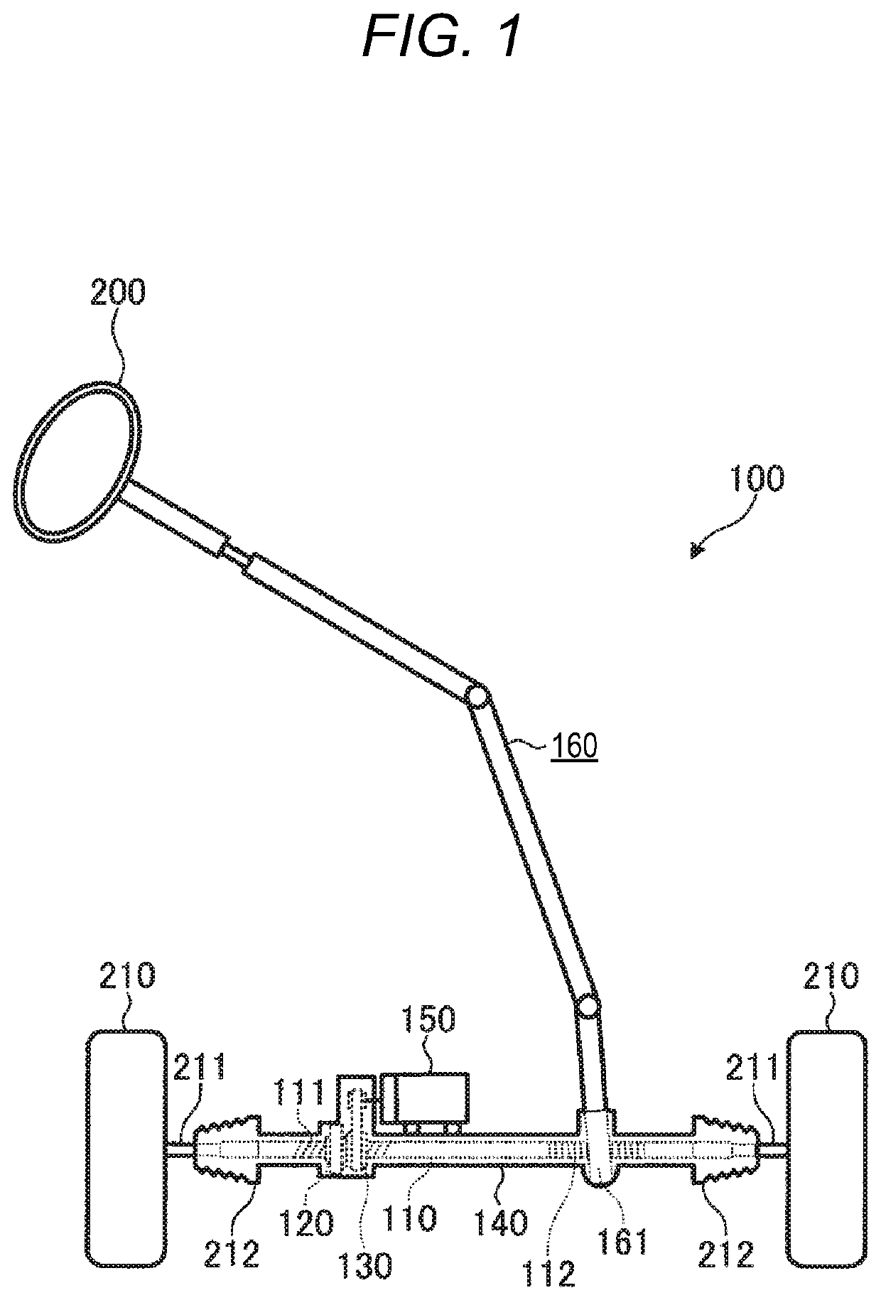
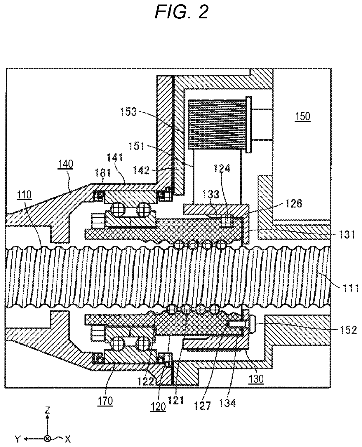
[0031]Next, embodiments of a steering device including a ball screw device according to an aspect of the present disclosure will be described with reference to the drawings. It should be noted that all embodiments described below show inclusive or specific examples. Numerical values, shapes, materials, constituent elements, arrangement positions and coupling forms of the constituent elements, steps, order of the steps, and the like shown in the following embodiment are merely examples, and are not intended to limit the present invention. In addition, among the constituent elements in the following embodiment, constituent elements that are not described in independent claims indicating an uppermost concept are described as any constituent elements.

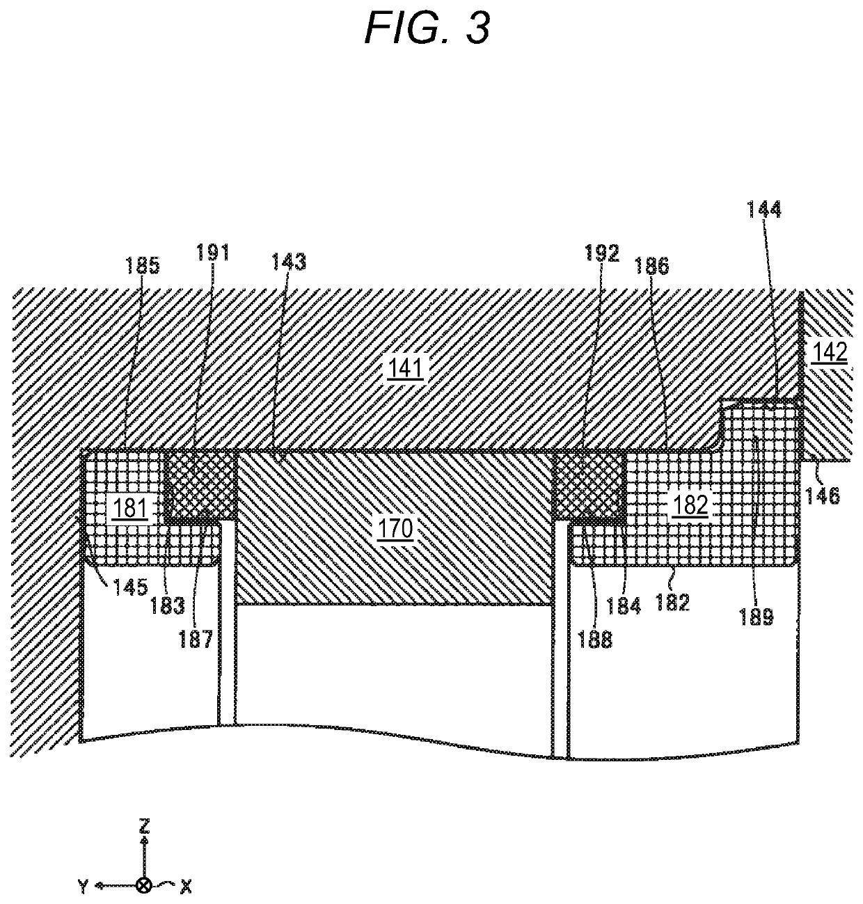
[0032]The drawings are schematic diagrams that are appropriately highlighted or omitted and whose ratios are adjusted appropriately for describing the present invention, and may be different from actual shapes, positional relationships, and...


PUM


Abstract

A ball screw device includes a screw shaft body, a ball nut, a housing, a bearing, an annular first biasing member and an annular second biasing member, and an annular first holding member and an annular second holding member. The housing includes a cylindrical first housing and a cylindrical second housing that are coupled to each other in a surface-contact state. The first housing includes a bearing holding portion that holds the bearing slidably in the axial direction. The second housing includes a pressing portion that protrudes radially inward. At least one of the first holding member and the second holding member generates a gap between the first housing and the second housing when the bearing, the first biasing member, the second biasing member, the first holding member, and the second holding member are wrongly mounted to one another.

Description

CROSS-REFERENCE TO RELATED APPLICATIONS[0001]This application is based on and claims priority under 35 USC 119 from Japanese Patent Application No. 2019-078795 filed on Apr. 17, 2019 and Japanese Patent Application No. 2019-083368 filed on Apr. 24, 2019, the contents of which are incorporated herein by reference.TECHNICAL FIELD[0002]The present invention relates to a ball screw device that rotates a ball nut to move a screw shaft body in an axial direction, and a steering device including the ball screw device.BACKGROUND ART[0003]A ball screw device includes a screw shaft that is formed with a spiral screw groove on an outer circumferential surface, and a ball nut that is screwed into the screw groove of the screw shaft via a plurality of balls. The ball nut is rotated to cause the screw shaft to linearly move.[0004]For example, as described in JP2013-147074A, a ball screw device used in a power steering device is desirable to reduce a gear striking noise by preventing a ball nut fr...

Claims


Application Information

Patent Timeline
IPC IPC(8): F16H25/22B62D5/04
CPCB62D5/0448B62D5/0421F16H25/2209B62D5/0424F16C19/184F16C27/066F16C35/067F16C2326/24
Inventor IINUMA, YUSUKE
Owner JTEKT CORP
Why Eureka
Try Eureka