Spinal alignment component

a technology of spine and component, applied in the field of spine alignment components, can solve the problems of poor health, reduced productivity of workforce, poor quality of life, etc., and achieve the effects of reducing costs, finely adjusting the length of the elongate member, and facilitating the transfer of the devi

Pending Publication Date: 2022-03-17
GROSS MACIEJ +1
View PDF0 Cites 2 Cited by
  • Summary
  • Abstract
  • Description
  • Claims
  • Application Information

AI Technical Summary

Benefits of technology

[0125]The variable length elongate member allows a single device to be used by a broader size range of wearers, thereby reducing the costs associated with providing multiple sizes of device and facilitating transfer of the device between wearers (e.g. for a shared device at, for example, a gym). This also enables the wearer to finely adjust the length of the elongate member for optimum fit, compared to the large jumps in elongate member length between different sized fixed length elongate member devices.
[0126]In some embodiments the securement system is incorporated into a bag. The bag may be a rucksack. In some embodiments a bag may be reversibly attached to the alignment device. In some embodiments the securement system is incorporated into clothing. The clothing may comprise a vest or gilet. This enables the device to be used easily during everyday activities and makes the device more aesthetically pleasing. The device is provided with additional useful functions, such as the ability to transport personal items.
[0127]In some embodiments the wearable alignment device comprises a sensor. In some embodiments the sensor is configured to generate sensor data. In some embodiments the sensor is configured to sense contact between a contact portion and the wearer's body. In some embodiments the sensor is configured to sense the orientation of the rigid elongate member, for example the orientation relative to the vertical. This is important because the preferred orientation when in ideal alignment is vertical, i.e. a position in which the line which passes through the apex of the sacral spine, the apex of the thoracic spine and the back of the occipital head is parallel with the vertical. A person adopting this position places the minimum level of strain on the back and the risk of injury is reduced.

Problems solved by technology

Poor posture may lead to poor health, sickness, pain and injury.
Workforce productivity is reduced due to lost work days and quality of life is compromised by avoidable injury.
Disadvantages of this approach include the requirement for a postural expert, the lack of mobility during training and that the method is not hands free.
Therefore, training is restricted to short time periods and while not carrying out everyday activities or exercise.
As a result, the wearer does not adapt mentally or physically to maintain ideal alignment and will therefore become reliant on the device to provide ideal alignment.
Furthermore, known devices are cumbersome and difficult to attach to the wearer, necessitating assistance from a third party for a wearer wishing to wear the device.
This is not always practical since a wearer may wish to use such a device on a daily basis for optimum long-term posture improvement results.
They are large and not compactable, making storage difficult when not in use.
Fixed size devices are only suitable for a narrow size range of wearers.
These devices often focus on the posture of one portion of the body, such as the abdomen, and do not result in ideal alignment of the whole body.
During everyday activities and exercise, unaccounted for changes in position result in the device communicating false feedback.
This confuses the wearer, renders the device unusable during such activity and may encourage non-ideal alignment and incorrect posture.

Method used


Image

  • Spinal alignment component
  • Spinal alignment component
  • Spinal alignment component

Examples


first embodiment

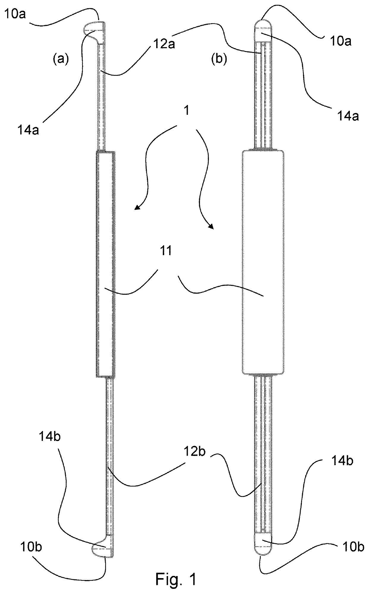
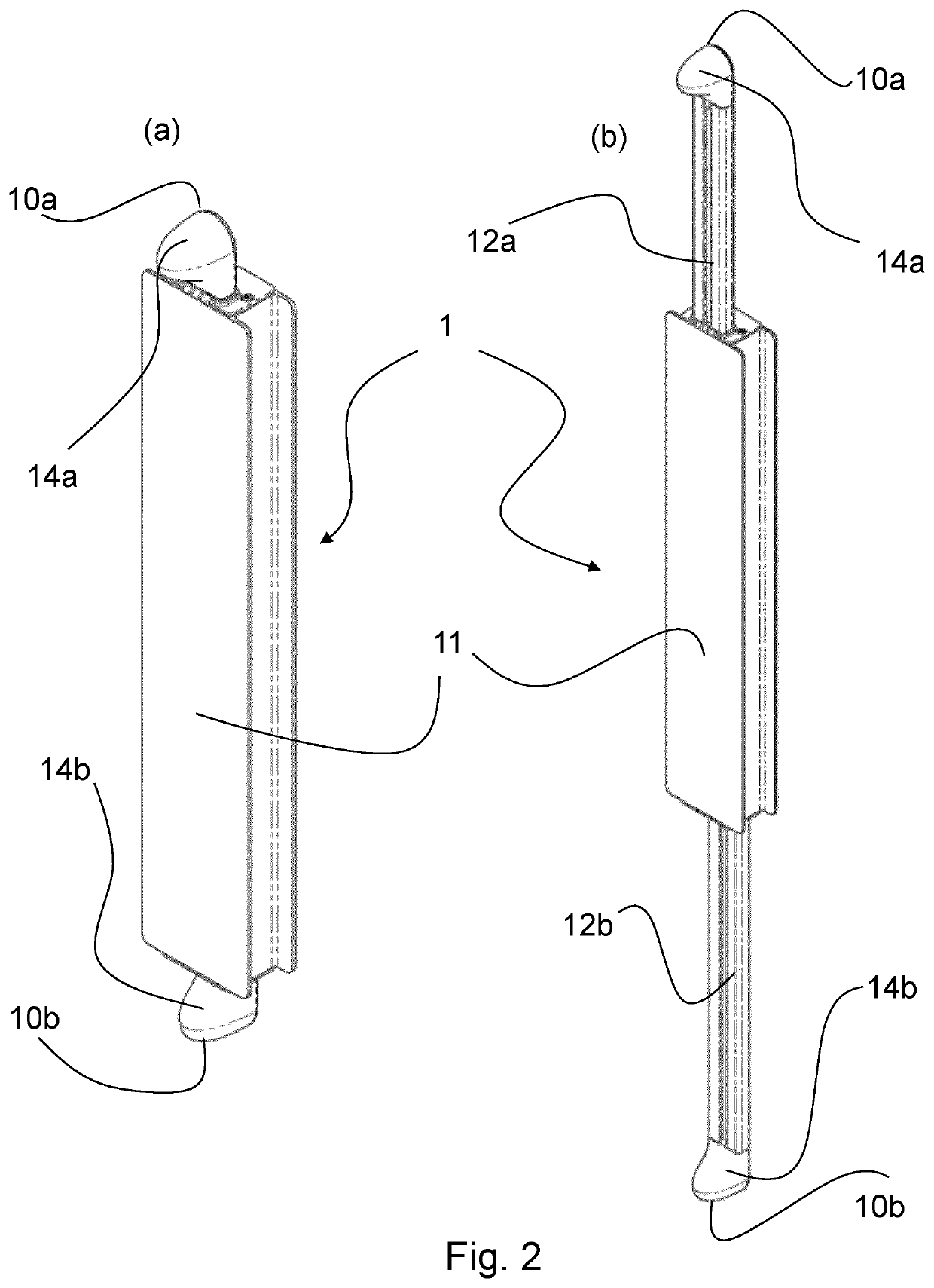
[0162]FIG. 1 shows a side elevation (a) and rear elevation (b) of a spinal alignment component 1 according to the invention.

[0163]The spinal alignment component is made up of an elongate housing 11 made of rigid plastics material which independently receives and guides two rigid elongate members 12a and 12b. First rigid elongate member 12a extends upwardly (as seen in FIG. 1) out of the housing 11 through a first aperture (not shown) and second rigid elongate member 12b extends downwardly (as seen in FIG. 1) out of the housing 11 through a second aperture (not shown). Each of the first and second rigid elongate members 12a, 12b are slidably engaged with the housing 11 within respective internal channels defined by the housing 11. FIG. 1 shows the component in a fully extended configuration, with each of the first and second rigid elongate members 12a, 12b extended out of the housing 11 to the greatest extent possible. Further extension may be prevented by a detent mechanism within t...


PUM


Abstract

A spinal alignment component is adapted for incorporation into a wearable spinal alignment apparatus and comprises a first rigid elongate member comprising a first distal end and a second rigid elongate member comprising a second distal end. The first rigid elongate member and the second rigid elongate member are independently movable relative to one another to adjust the displacement between the first distal end and the second distal end. Wearable spinal alignment apparatus incorporating the component is also described. The component and apparatus offers a means to encourage ideal alignment and correct the posture of a wearer.

Description

RELATED APPLICATION[0001]This application is related to and claims priority from United Kingdom patent application number 1907095.2 filed 20 May 2019, the contents of which are incorporated herein by reference in their entirety.TECHNICAL FIELD[0002]The present invention relates to a spinal alignment component and, more particularly, to a spinal alignment component comprising first and second rigid elongate members which are independently movable. The invention also relates to wearable alignment devices, such as wearable spinal alignment apparatus, comprising the spinal alignment component and uses of the spinal alignment component for correcting posture during everyday activities and exercise.BACKGROUND OF THE INVENTION[0003]Poor posture may lead to poor health, sickness, pain and injury. Workforce productivity is reduced due to lost work days and quality of life is compromised by avoidable injury.[0004]Correct posture is brought about by ideal alignment. Ideal alignment is the posi...

Claims


Application Information

Patent Timeline
Patent Type & Authority Applications(United States)
IPC IPC(8): A61F5/02A61B5/00A45F3/04A45F3/00
CPCA61F5/026A61B5/6831A61B5/6812A45F2003/001A45F3/04A61B5/6843A61F5/028A61F5/0102A61B5/486A61B5/6802A61B5/6844
Inventor GROSS, MACIEJATKINSON, TOBY
Owner GROSS MACIEJ
Why Eureka
Try Eureka