
Atmospheric water generator

a generator and atmosphere technology, applied in the direction of evaporation, sustainable building, separation process, etc., can solve the problems of reducing the volume of the apparatus, high energy cost of a given amount of extracted water, and noise level involved in the production of water

Pending Publication Date: 2022-03-17
WATERGEN LTD
View PDF0 Cites 1 Cited by
  • Summary
  • Abstract
  • Description
  • Claims
  • Application Information

AI Technical Summary

Benefits of technology

The invention provides solutions to the challenges and drawbacks of atmospheric water generators (AWGs) by introducing an enclosure with an air inlet and an air outlet, an evaporator assembly, a condenser, and a blower. The airflow from the air inlet through the evaporator assembly and out through the air outlet can be directed to cool the electricity panel or the porous barrier in the airflow refrigeration cycle. The blower can be positioned downstream of the evaporator and can be centralized to the flow-lines of the airflow exiting the evaporator. These technical effects improve the efficiency and performance of AWGs.

Problems solved by technology

While this method is highly available, there are several obstacles for making this method competitive with alternative water dispensers which draw their water from the regular pipeline or from mineral water tanks.
To name a few, these challenges include reducing the high amount of heat energy needed to be evacuated, leading to a high energetic cost for a given amount of extracted water, the noise level involved with the production of water, matching production with the consumption demand, reducing the volume of the apparatus and more.

Method used


Image

  • Atmospheric water generator
  • Atmospheric water generator
  • Atmospheric water generator

Examples


specific embodiments

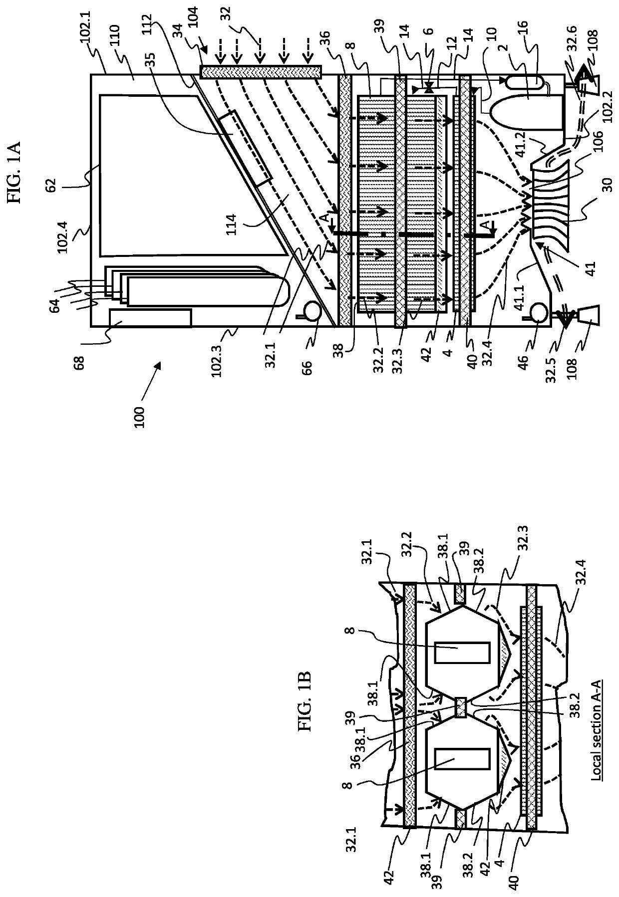
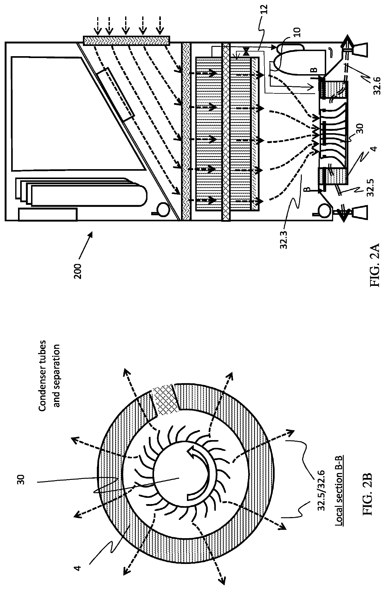
[0042]Reference is now made to FIGS. 1A and 1B depicting an AWG apparatus 100 according to an embodiment of the invention. The apparatus should comprise many components that for sake of convenience are not shown in FIG. 1 or the figures to come such as a utility line, controller, temperature sensor(s), push button(s) and some other control means. A person skilled in the art would know how to extrapolate the details provided herein into a fully operative AWG. The apparatus 100 comprises an enclosure 102 having a back sidewall 102.1, a bottom wall 102.2, a front wall 102.3 and a top wall 102.4, an environment air inlet 104 (equipped with a coarse air filter 34) and air outlet 106. The enclosure is connected to a set of legs 108 which elevate the bottom wall 102.2 from the ground and enable leveling the apparatus. The enclosure 102 accommodates a water generating refrigeration cycle, and a generated water system.

[0043]Some of the volume occupying components of the generated water syste...


PUM

PropertyMeasurementUnit
Flow rateaaaaaaaaaa

Abstract

The invention discloses an AWG having improvements designed to reduce noise, improve uniform airflow through the evaporator of the AWG and reduce energy consumption. In one embodiment the AWG includes an air inlet located in one of the sidewalls of the enclosure and a blower located in proximity to the air outlet at the bottom wall of the enclosure.

Description

TECHNICAL FIELD[0001]The present invention relates to the field of atmospheric water generators.BACKGROUND OF THE INVENTION[0002]Extraction of water from air by atmospheric water generators, is well known and typically involves enforcement of condensation conditions of air containing water vapor (i.e. humid air) by lowering its temperature below the dew point temperature, thereby causing some vapor to condensate and liquid water is then released from the carrying air. While this method is highly available, there are several obstacles for making this method competitive with alternative water dispensers which draw their water from the regular pipeline or from mineral water tanks. To name a few, these challenges include reducing the high amount of heat energy needed to be evacuated, leading to a high energetic cost for a given amount of extracted water, the noise level involved with the production of water, matching production with the consumption demand, reducing the volume of the app...

Claims


Application Information

Patent Timeline
IPC IPC(8): E03B3/28B01D53/26
CPCE03B3/28B01D53/265B01D1/14B01D5/006Y02A20/00B01D5/00Y02B10/50
Inventor DULBERG, SHARONBLUMENTHAL, YANIR RICHARDPERY, MORANCHERNIN, GUY EVGENINECHEMIA, CHEN
Owner WATERGEN LTD
Learn More