Method of adjusting optical apparatus, adjustment support method, optical system, and optical apparatus
- Summary
- Abstract
- Description
- Claims
- Application Information
AI Technical Summary
Benefits of technology
Problems solved by technology
Method used
Image

Examples
first embodiment
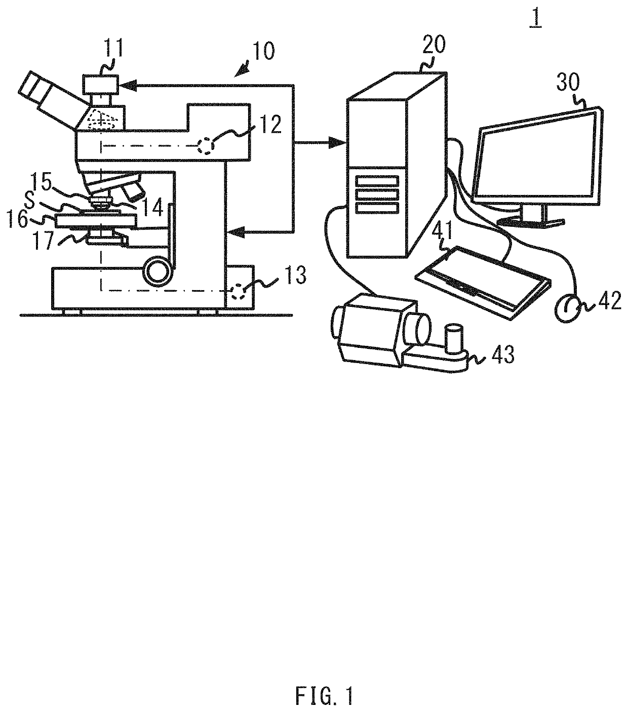
[0091]FIG. 5 is a diagram illustrating a configuration of a microscope 100. A microscope system according to the present embodiment differs from the microscope system 1 illustrated in FIG. 1 in that it includes the microscope 100 instead of the microscope 10. Other components are similar to those in the microscope system 1.
[0092]The microscope 100 is a microscope that performs bright-field observation using epi-illumination, and includes an objective lens 101, modulation elements used by being switched (a modulation element 102 and a modulation element 103), a splitter 104, an imaging lens 105, an image pickup device 106, and a lens 107.
[0093]The modulation element 103 is an optical element that emphasizes a spherical aberration of an image to be acquired. When the modulation element 103 is inserted into an observation optical path and is used for observation, the spherical aberration is more emphasized than when the modulation element 103 is not used. Accordingly, the spherical abe...
second embodiment
[0135]FIG. 48 is a flowchart of semi-automatic adjustment processing according to the present embodiment. A configuration of a microscope system according to the present embodiment is similar to that of the microscope system according to the first embodiment. The microscope system according to the present embodiment differs from the microscope system according to the first embodiment in that it performs the semi-automatic adjustment processing illustrated in FIG. 48 instead of the automatic adjustment processing illustrated in FIG. 7.
[0136]When the semi-automatic adjustment processing illustrated in FIG. 48 is started, a control device 20 first causes a microscope 100 to acquire a first image (step S31). The control device 20 causes a display device 30 to display the image acquired by the microscope 100 (step S32). In the present embodiment, a user manually arranges a first modulation element on an optical path before step S31.
[0137]Then, the control device 20 determines whether or ...
third embodiment
[0144]FIG. 49 is a flowchart of automatic adjustment processing according to the present embodiment. A configuration of a microscope system according to the present embodiment is similar to that of the microscope system according to the first embodiment. The microscope system according to the present embodiment differs from the microscope system according to the first embodiment in that it performs the automatic adjustment processing illustrated in FIG. 49 instead of the automatic adjustment processing illustrated in FIG. 7. The microscope system according to the present embodiment differs from the microscope system according to the first embodiment in that a first image and a second image are generated by image processing in the automatic adjustment processing illustrated in FIG. 49, although a first image and a second image to be acquired are switched by switching modulation elements in the automatic adjustment processing illustrated in FIG. 7.
[0145]When the automatic adjustment p...
PUM
 Abstract
Description
Claims
Application Information
 - Generate Ideas
- Intellectual Property
- Life Sciences
- Materials
- Tech Scout
- Unparalleled Data Quality
- Higher Quality Content
- 60% Fewer Hallucinations
Browse by: Latest US Patents, China's latest patents, Technical Efficacy Thesaurus, Application Domain, Technology Topic, Popular Technical Reports.
© 2025 PatSnap. All rights reserved.Legal|Privacy policy|Modern Slavery Act Transparency Statement|Sitemap|About US| Contact US: help@patsnap.com