Method and device for heating a mould

a mold and heating technology, applied in the field of methods and devices for heating molds, can solve the problems of multiple high-power, high-frequency generators to power the induction heating means for each mold, and high-power die couple, and achieve the effects of reducing the thermal resistance of the contact, promoting heat transfer, and high thermal conductivity

Pending Publication Date: 2022-03-24
ROCTOOL SAS
View PDF2 Cites 1 Cited by
  • Summary
  • Abstract
  • Description
  • Claims
  • Application Information

AI Technical Summary

Benefits of technology

[0024]Advantageously, the heat accumulator comprises a phase changing material. This embodiment makes it possible to store thermal energy in the latent phase change heat of said material.
[0025]According to an embodiment the heat transfer surface of the first and the second heating plates comprise a thin strip made of malleable and compressible heat conducting material. Such a strip acts as a shape adaptation layer at the interface between the receiving surface of the die and the heat transfer surface of the plate or of the heat accumulator, reducing the thermal resistance of the contact and promoting heat transfer.
[0026]Advantageously the dies are made of a material having a higher thermal conductivity than the heating plates, preferably 2 to 3 times higher. Example of such materials when the heating plates are made of a ferromagnetic steel are aluminum alloys, copper alloys, graphite or nickel without this list being limiting. The high thermal conductivity and thermal diffusivity of the material making the dies promotes rapid heating and quick homogenization of the temperatures on the molding surfaces.
[0027]According to an embodiment, the dies comprise cooling channels for the circulation of a heat transfer fluid. This allows to cool the dies quicker after a molding or shaping cycle and to reduce cycle times.

Problems solved by technology

However, when several part types are made, each requiring a specific dies couple, setting up induction heating means and cooling means for each die couple is costly.
Having multiple high power, commonly 100 kW, and high frequency generators to power the induction means for each mold is also costly,

Method used


Image

  • Method and device for heating a mould
  • Method and device for heating a mould
  • Method and device for heating a mould

Examples


Embodiment Construction

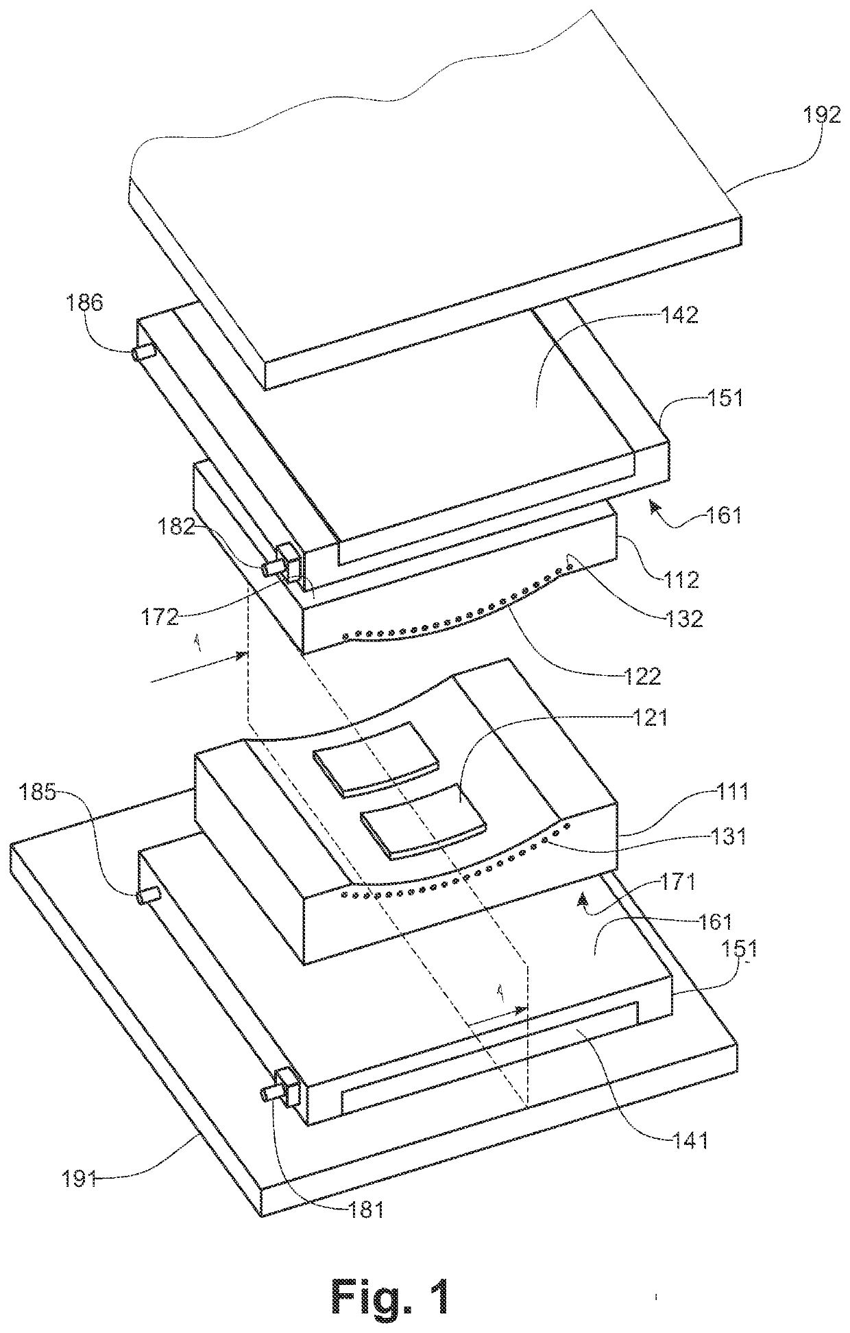
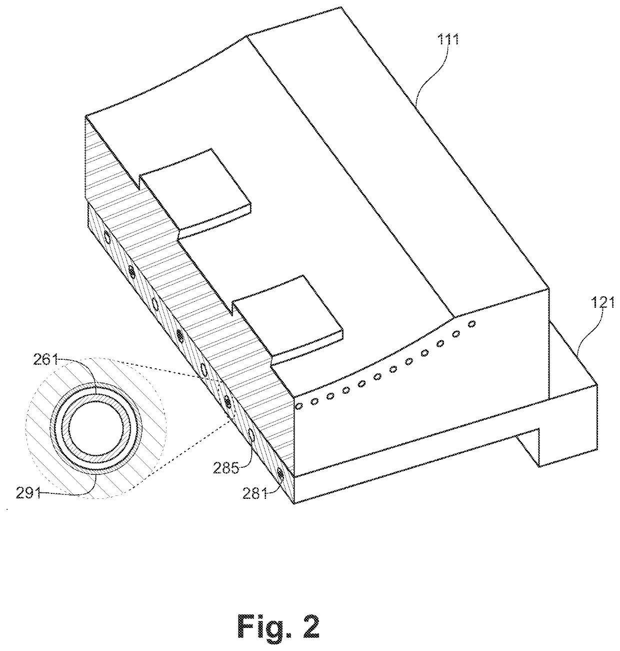
[0037]FIG. 1, according to an exemplary embodiment the mold of the invention comprises 2 dies (111, 112), each die comprises one or more molding surfaces (121, 122) the shape of which is reproduced by the part being formed, the molding surfaces of both dies forming a cavity when the two dies are brought in contact to one another, that is, when the mold is closed.

[0038]Such a pair for dies may be used for various shaping or molding operations like stamping, consolidation in shape, injection molding or combination thereof without these examples being limiting.

[0039]In a stamping, operation a flat blank made of a composite material comprising reinforcing fibers in a thermoplastic polymer matrix is placed on a first die (111). The temperature of the blank is raised to a level where the polymer reaches a pasty state, as for instance by heating the first die, the second die (112) is moved towards the first die, thus closing the mold and urging the flat blank to the shape of the cavity. Th...


PUM

PropertyMeasurementUnit
poweraaaaaaaaaa
temperatureaaaaaaaaaa
holding temperatureaaaaaaaaaa

Abstract

A mold to shape a material having a polymer matrix. The mold includes a first and a second die having molding surfaces. The molding surfaces delimit a molding cavity configured to shape the material when the first and the second dies are brought in contact with each other and the mold is closed. The heating plates include a ferromagnetic material configured to be heated by induction, and to transfer heat from a heat transfer surface of the heating plate to a receiving surface of the dies, other than the molding surfaces. The heating plates include heating and cooling channels. The heating channels of the heating plates have an inductor. The cooling channels of the heating plates are configured to circulate a heat transfer fluid.

Description

RELATED APPLICATIONS[0001]This application is a continuation-in-part of pending U.S. application Ser. No. 16 / 098,859 filed Feb. 19, 2019, which is a § 371 application from PCT / EP2017 / 061239 filed May 10, 2017, which claims priority from French Patent Application No. 16 70219 filed May 10, 2016, each of which is herein incorporated by reference in its entirety.TECHNICAL FIELD[0002]The invention relates to a method and a device for heating a mold. The invention is more particularly but not exclusively suitable for heating a mold used to shape and consolidate in shape plastic or composite articles. Such a mold comprises a molding cavity inside which the article is shaped. Said cavity is delimited by molding surfaces, the shape of which is reproduced by the shaped part.[0003]Said molding surfaces are supported by a least two shells that can be separated from each other so as to open the mold and remove the solidified part.[0004]The invention applies to various shaping or molding techniq...

Claims


Application Information

Patent Timeline
Patent Type & Authority Applications(United States)
IPC IPC(8): B29C35/08B29C33/06B29C33/04B29C33/38
CPCB29C35/0805B29C33/06B29C2035/0811B29C33/38B29C33/04B29C2045/7368B29C2045/7393B29C45/73
Inventor FEIGENBLUM, JOSÉ
Owner ROCTOOL SAS
Why Eureka
Try Eureka