
Method for digitally characterizing the permeability of rock

a technology of permeability and rock, applied in the field of characterizing can solve the problems of overestimation of the quantity of hydrocarbon fluid, improper spacing of wells, and significant overestimation, and achieve the effect of correcting the permeability of rock

Pending Publication Date: 2022-03-31
SHELL OIL CO
View PDF0 Cites 0 Cited by
  • Summary
  • Abstract
  • Description
  • Claims
  • Application Information

AI Technical Summary

Benefits of technology

The present invention can be adapted and practiced in different ways than described in the disclosed embodiments. The invention can be modified and combined in various ways as long as the benefits are achieved. The details of construction and design can be changed, and all such variations are within the scope of the invention. The invention described herein can be practiced without certain elements or optional elements being specifically disclosed herein. The invention can be understood to encompass a range of numbers and ranges disclosed herein. The terms in the claims have their plain, ordinary meaning, and the indefinitive article "a" or "an" means one or more than one of the element it introduces.

Problems solved by technology

For example, overestimating the absolute permeability (hereinafter the “permeability”) of the rock of a hydrocarbon-containing formation may lead to significant overestimation of fluid flow through the formation and, therefore, overestimation of the quantity of hydrocarbon fluids that may be produced from the formation.
Overestimation of the permeability of the rock of a hydrocarbon-containing formation may lead to improper spacing of wells, or, in a worst-case scenario, the development of a formation that may not provide adequate commercial production of hydrocarbons.
Such tests, however, require substantial time and are quite expensive.
Further, the number of samples that may be processed is relatively limited due to the time and expense required to conduct each test.
This bias cannot be accounted for by differences in rock microstructures generated by various segmentation algorithms since such differences are relatively minor as long as all phases are segmented consistently.
As such, current digital rock methods are relatively inaccurate and overestimate the true permeability of hydrocarbon-containing formation rock.

Method used


Image

  • Method for digitally characterizing the permeability of rock
  • Method for digitally characterizing the permeability of rock
  • Method for digitally characterizing the permeability of rock

Examples


example

[0062]The following non-limiting example of an embodiment of the method of the present invention as claimed herein is provided for illustrative purposes only.

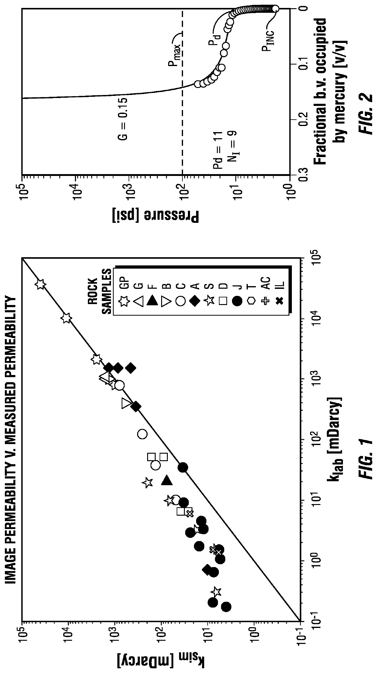
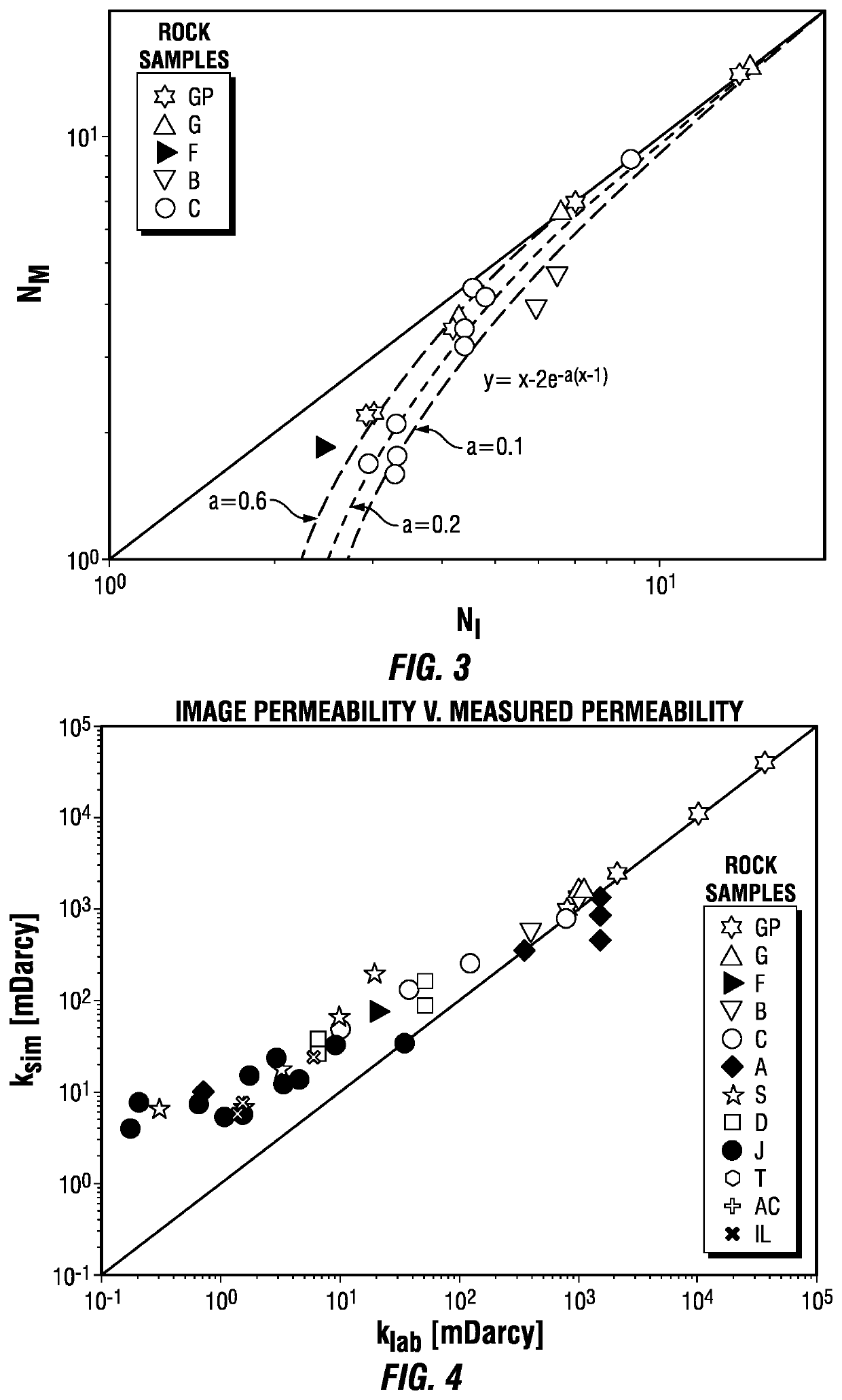
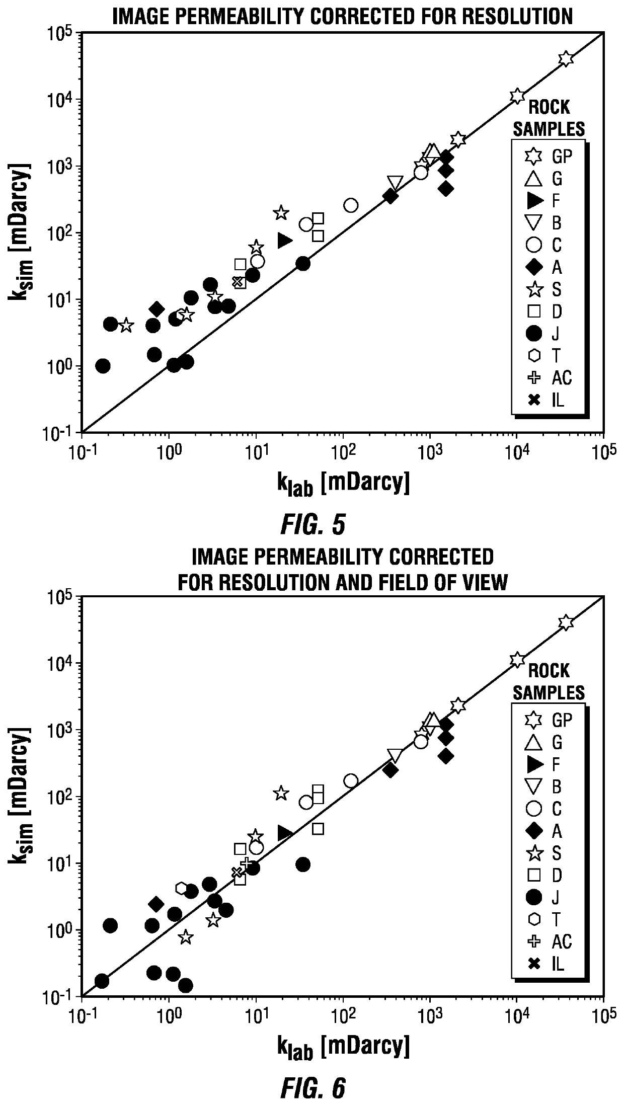
[0063]The corrected image permeability of twelve sandstone samples from separate hydrocarbon-containing formations was determined in accordance with the method of the present invention and was compared with the true permeability of the sandstones as determined by physical measurements.

[0064]Twelve core samples of sandstone were recovered from separate hydrocarbon-containing formations. The true permeability of each of the samples was determined in accordance with the industry standard of laminar flow brine injection into the samples.

[0065]The permeability of each of the sandstone samples was then estimated by digital rock imaging. Mini-plugs of each of the samples were extracted from the original cores. The mini-plug samples were three-dimensionally imaged by micro-CT imaging at ambient temperature. The mini-plug samples were s...


PUM

PropertyMeasurementUnit
permeabilityaaaaaaaaaa
image permeabilityaaaaaaaaaa
capillary pressureaaaaaaaaaa

Abstract

The present invention provides a method for estimating the permeability of rock from a digital image of the rock. A three-dimensional image of a rock is obtained and segmented, and an image permeability is determined from the segmented image of the rock. Permeability correction factors are obtained from the segmented image and from a non-wetting liquid capillary pressure curve derived from the segmented image, and the permeability correction parameters are applied to the image permeability to obtain a corrected image permeability of the rock.

Description

FIELD OF THE INVENTION[0001]The present invention relates to a method of characterizing the permeability of rock. In particular, the present invention relates to a method of characterizing the permeability of a rock from a three-dimensional image of the rock.BACKGROUND OF THE INVENTION[0002]Accurate determination of petrophysical characteristics of rock such as porosity and permeability within a hydrocarbon-containing reservoir is important in determining whether to select the hydrocarbon-containing reservoir for development, as well as developing and managing the hydrocarbon-containing reservoir. For example, overestimating the absolute permeability (hereinafter the “permeability”) of the rock of a hydrocarbon-containing formation may lead to significant overestimation of fluid flow through the formation and, therefore, overestimation of the quantity of hydrocarbon fluids that may be produced from the formation. Overestimation of the permeability of the rock of a hydrocarbon-contai...

Claims


Application Information

Patent Timeline
Patent Type & Authority Applications(United States)
IPC IPC(8): G01N15/08G01N33/24G01N23/046G01N23/083G06T7/11
CPCG01N15/08G01N33/24G01N23/046G01N23/083G06T7/11G06T2207/20081G01N2223/04G01N2223/616G01N2223/419G06T2207/10081G06T2207/30181G01N2015/0846G01N15/088G01N2223/305G06T2207/20084
Inventor SAXENA, NISHANKHOWS, AMIE MARIEHOFMANN, RONNYAPPEL, MATTHIASFREEMAN, JOHN JUSTIN
Owner SHELL OIL CO
Learn More