Projection system, control device, and image projection method

Pending Publication Date: 2022-03-31
SEIKO EPSON CORP
View PDF6 Cites 1 Cited by
  • Summary
  • Abstract
  • Description
  • Claims
  • Application Information

AI Technical Summary

Benefits of technology

The present patent is about a projection system that projects image light onto a screen using a screen forming device that ejects liquid onto the screen. The system includes a control device that controls the projection device and the screen forming device based on three-dimensional shape data that is divided in the Y-axis direction to generate sectional shape data. The control device also matches the coordinates of the sectional shape data with the pixels of the projection device and the heights of the ejection space from the nozzles of the screen forming device. The system can project the image light onto the screen based on the sectional shape data and the correlation between the coordinates of the sectional shape data, pixels with which the projection device draws the image, the nozzles of the screen forming device, and the heights of the ejection space. The technical effect of this patent is to provide a more precise and accurate method for projecting images onto a screen using a screen forming device and a projection device that works together to create a seamless and immersive experience for the viewer.

Problems solved by technology

Therefore, it is difficult to display an image having cubic effect.

Method used


Image

  • Projection system, control device, and image projection method
  • Projection system, control device, and image projection method
  • Projection system, control device, and image projection method

Examples


first embodiment

1. First Embodiment

1-1. Overall Configuration of a Projection System 1

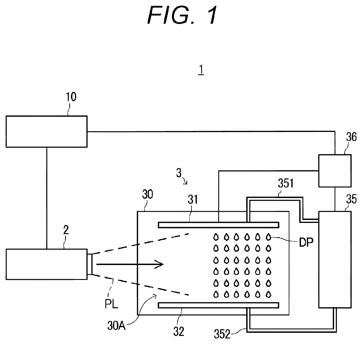
[0041]FIG. 1 is a diagram showing a schematic configuration of a projection system 1.

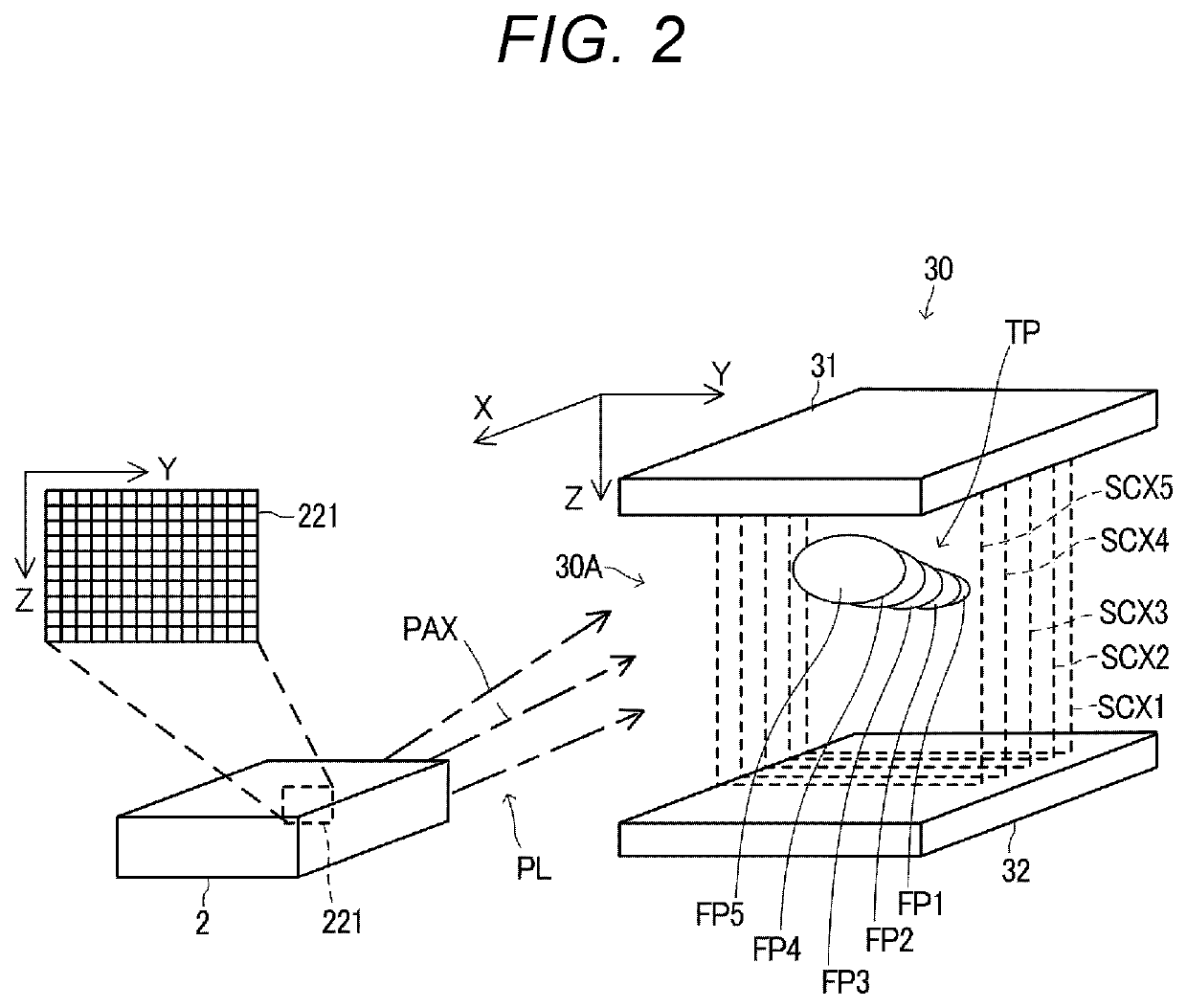
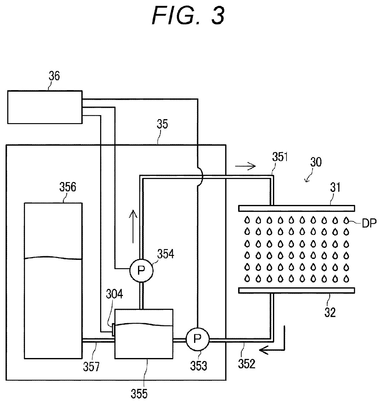
[0042]The projection system 1 includes a projector 2, a screen forming device 3, and a control device 10. The projector 2 projects image light PL according to control by the control device 10. The screen forming device 3 includes a screen forming section 30. The screen forming section 30 includes an ejection head 31 that ejects liquid and a collection unit 32 that collects the liquid ejected by the ejection head 31. The screen forming section 30 causes the liquid to flow down to an ejection space 30A between the ejection head 31 and the collection unit 32 as drop-like droplets DP.

[0043]The control device 10 controls the projector 2 to project the image light PL and controls the screen forming device 3 to form a screen. The projector 2 corresponds to an example of the projection device.

[0044]The projection head 31 includes a plural...

second embodiment

2. Second Embodiment

[0166]FIG. 16 is a flowchart showing the operation of the projection system 1 in a second embodiment. FIG. 17 is an explanatory diagram showing transition of a projection state in the second embodiment.

[0167]In the second embodiment, since the configuration of the projection system 1 is the same as the configuration explained in the first embodiment, illustration and explanation of the configuration are omitted.

[0168]In the operation shown in FIG. 16, steps S41 to S46 and steps S49 to S50 are common to FIG. 12.

[0169]The projection system 1 selects, according to the control by the control device 10, the nozzle rows 34 of the ejection head 31 lined in the X-axis direction with the head driving section 302. The head driving section 302 ejects the droplets DP once from all the nozzles 33 forming the selected nozzle row 34 (step S55). The projector 2 projects a sectional image corresponding to the nozzle row Xa (step S56).

[0170]Thereafter, the control device 10 shifts...

third embodiment

3. Third Embodiment

[0182]FIG. 18 is a flowchart showing the operation of the projection system 1 in a third embodiment. FIG. 19 is an explanatory diagram showing transition of a projection state in the third embodiment.

[0183]In the third embodiment, since the configuration of the projection system 1 is the same as the configuration explained in the first embodiment, illustration and explanation of the configuration are omitted.

[0184]In the operation shown in FIG. 18, steps S41 to S46 and steps S49 to S50 are common to FIG. 12.

[0185]The projection system 1 selects, according to the control by the control device 10, the nozzle row 34 out of the nozzle rows 34 of the ejection head 31 lined in the X-axis direction with the head driving section 302. The head driving section 302 continuously ejects the droplets DP a plurality of times from all the nozzles 33 forming the selected nozzle row 34 (step S61). The projector 2 projects a sectional image corresponding to the nozzle row Xa (step S...


PUM


Abstract

A projection system includes a screen forming device configured to form a screen by ejecting liquid from a plurality of nozzles and a projector, acquires three-dimensional shape data formed by a three-dimensional coordinate system having an X axis, a Y axis, and a Z axis, divides the three-dimensional shape data in an X-axis direction to generate sectional shape data, acquires coordinates of the sectional shape data, executes matching processing for correlating the coordinates of the sectional shape data, pixels with which the projector draws an image, the nozzles of the screen forming device, and heights in an ejection space of the liquid ejected from the nozzles, and projects an image onto the screen according to the correlation by the matching processing.

Description

[0001]The present application is based on, and claims priority from JP Application Serial Number 2020-161700, filed Sep. 28, 2020, the disclosure of which is hereby incorporated by reference herein in its entirety.BACKGROUND1. Technical Field[0002]The present disclosure relates to a projection system, a control device, and an image projection method.2. Related Art[0003]There has been known a technique for forming a screen with liquid and projecting an image onto the screen (see, for example, JP-A-2015-121655 (Patent Literature 1)). A projection system described in Patent Literature 1 blows mist generated by an ultrasonic transducer upward with a fan and forms a screen. The projection system projects, with a projector, an image onto the screen formed by the mist. The projection system drives the fan for blowing out the mist to thereby form a screen having size corresponding to the projected image.[0004]An image projected by a configuration described in Patent Literature 1 is a plane ...

Claims


Application Information

Patent Timeline
IPC IPC(8): G03B21/608G03B21/14G03B21/20
CPCG03B21/608G03B21/2033G03B21/142H04N13/39
Inventor YOKOO, TOMOHIROAOKI, YOSHISADA
Owner SEIKO EPSON CORP
Why Eureka
Try Eureka