
Hybrid method for 3D shape measurement

a 3d shape and hybrid technology, applied in the field of optical imagery, can solve the problems of affecting the speed of measurement, and affecting the accuracy of measurement, and achieve the effect of eliminating the problems of nonlinear gamma effect and measuring speed

Inactive Publication Date: 2011-04-07
IOWA STATE UNIV RES FOUND
View PDF13 Cites 136 Cited by
  • Summary
  • Abstract
  • Description
  • Claims
  • Application Information

AI Technical Summary

Benefits of technology

[0010]Therefore, it is a primary object, feature, or advantage of the present invention to improve over the state of the art.
[0011]It is a further object, feature, or advantages of the present invention to provide for real-time three-dimensional imaging.
[0012]It is a further object, feature, or advantage of the present invention to provide measurement speed which is significantly faster than existing high-resolution, real-time 3D shape measurement techniques.
[0013]It is a still further object, feature, or advantage of the present invention to measure step-height objects, which is not possible using prior art high-resolution, real-time 3D shape measurement techniques.
[0014]Yet another object, feature, or advantage of the present invention is to allow for simultaneous measurements of multiple objects.
[0015]It is another object, feature, or advantage of the present invention to provide a 3D imaging technique which may be used in complex applications such as measuring live heart 3D shapes accurately.

Problems solved by technology

However, the measurement accuracy is affected, to a various degree by the color of the object.
Despite the success of the technique, several major limitations are present.
These include limitations associated with single connected patch measurement, smooth surface measurements and speed.
Thus, it is impossible to measure multiple objects simultaneously.
“Smooth” surfaces measurements is an additional significant limitation.
Maximum speed of 120 Hz is another significant limitation.
However, the 3D measurement speed is slow and it is clearly not feasible to measure the motion of the heart.
Because the live beating heart deforms rapidly, there is no existing 3D imaging technique can capture the geometric motion.
Hence, the existing techniques require immobilization of the heart which makes it impossible to understand the mechanical function besides the electrophysiology.

Method used


Image

  • Hybrid method for 3D shape measurement
  • Hybrid method for 3D shape measurement
  • Hybrid method for 3D shape measurement

Examples


Embodiment Construction

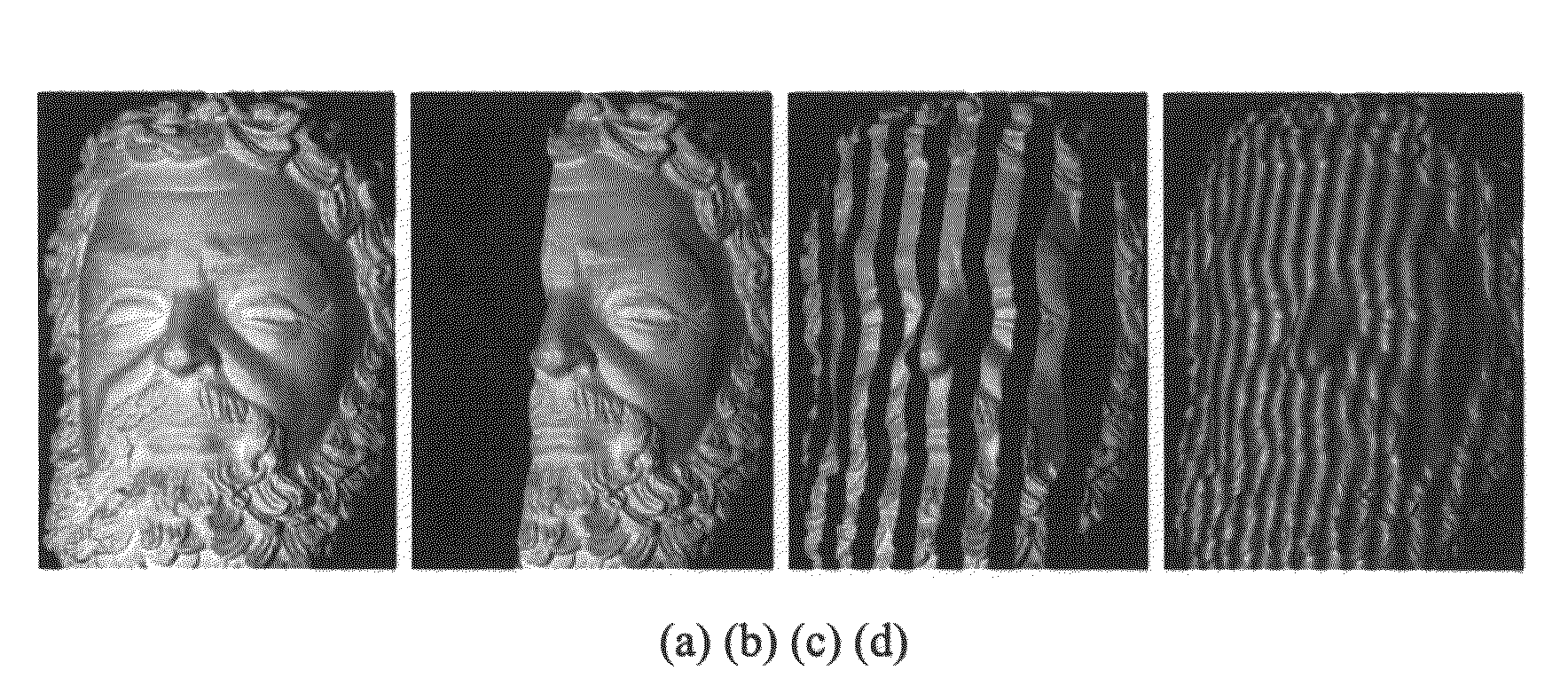
[0061]The patent or application file contains at least one drawing executed in color. Copies of this patent or patent application publication with color drawing(s) will be provided by the Office upon request and payment of the necessary fee.

1. Overview

[0062]The present invention includes a number of different aspects which may be independent of one another. A first aspect relates to generating sinusoidal fringe patterns by defocusing binary patterns. This allow for high resolution, super-fast 3D shape measurement. The method may be applied to numerous fields where fast 3D shape measurement is needed including, without limitation, medical sciences, homeland security, manufacturing, entertainment, and other applications. The method overcomes limitations of existing real-time 3D shape measurement technologies, especially those issues associated with image generation speed and image switching speed associated with conventional sinusoidal fringe generation. The method allows for increasi...


PUM


Abstract

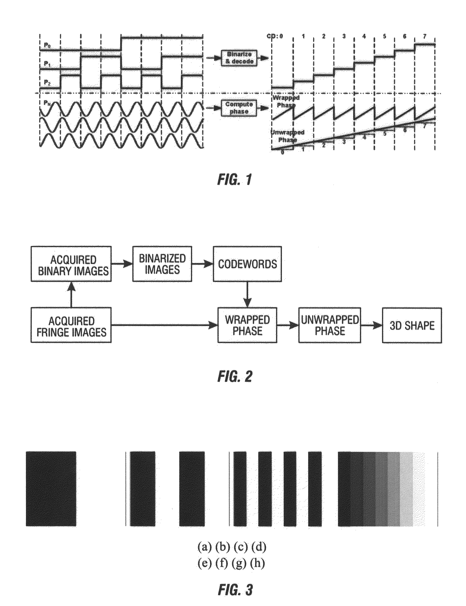
A method for three-dimensional shape measurement provides for generating sinusoidal fringe patterns by defocusing binary patterns. A method for three-dimensional shape measurement may include (a) projecting a plurality of binary patterns onto at least one object; (b) projecting three phase-shifted fringe patterns onto the at least one object; (c) capturing images of the at least one object with the binary patterns and the phase-shifted fringe patterns; (d) obtaining codewords from the binary patterns; (e) calculating a wrapped phase map from the phase-shifted fringe patterns; (f) applying the codewords to the wrapped phase map to produce an unwrapped phase map; and (g) computing coordinates using the unwrapped phase map for use in the three-dimensional shape measurement of the at least one object. A system for performing the method is also provided. The high-speed real-time 3D shape measurement may be used in numerous applications including medical science, biometrics, and entertainment.

Description

CROSS-REFERENCE TO RELATED APPLICATION[0001]This application claims the benefit of Provisional Application No. 61 / 249,108, filed Oct. 6, 2009, herein incorporated by reference in its entirety.FIELD OF THE INVENTION[0002]The present invention relates to optical imagery. More specifically, but not exclusively, the present invention relates to methods and systems for performing three dimensional (3D) shape measurement where sinusoidal fringe patterns are generated by defocusing binary patternsBACKGROUND OF THE PRIOR ART[0003]For real-time 3D shape measurement, techniques based on color (Geng 1996, Harding 1991, Huang et al. 1999, Zhang et al. 2002) have the potential to reach higher speed since the color contains more information. However, the measurement accuracy is affected, to a various degree by the color of the object. Recently, one of the present inventors has co-developed a technology for high-resolution real-time 3D shape measurement (Zhang & Huang 2006a,b) by utilizing fast ph...

Claims


Application Information

Patent Timeline
Patent Type & Authority Applications(United States)
IPC IPC(8): H04N13/02G01B11/22
CPCG01B11/245G01B11/2527G01B11/2513G06T2207/10016G06T2207/10028G06T2207/30048G06T2207/30201G06T7/521
Inventor SONG, ZHANGOLIVER, JAMES H.
Owner IOWA STATE UNIV RES FOUND
Learn More