Eureka AIR delivers breakthrough ideas for toughest innovation challenges, trusted by R&D personnel around the world.

Circuit breaker having internal transient recovery voltage capacitor assembly

a capacitor and circuit breaker technology, applied in the field of circuit breakers, can solve the problems of increasing manufacturing costs and expenses, thermal/dielectric failure of the circuit interrupter, and complicating the provision of sufficient clearance for at least certain components related to the circuit breaker

Pending Publication Date: 2022-04-07
HITACHI ENERGY SWITZERLAND AG
View PDF11 Cites 0 Cited by
  • Summary
  • Abstract
  • Description
  • Claims
  • Application Information

AI Technical Summary

Benefits of technology

The present invention is a circuit breaker with a capacitor assembly that can help to eliminate or reduce voltage spikes during power failures. The circuit breaker has a contact assembly with a moveable contact and a shield. The capacitor assembly has a transient recovery voltage capacitor that can help to stabilize the electrical power supply. The capacitor assembly can be housed within the enclosure of the circuit breaker or pole assembly. The technical effect of the invention is to improve the stability and reliability of the electrical power system by reducing voltage spikes and providing a more stable electrical power supply.

Problems solved by technology

Further, such TRV can attribute to unsuccessful interruption of the current, and thus, in at least certain situations, result in thermal / dielectric failure of the circuit interrupter.
Yet, such external line-to-ground TRV capacitors typically require additional external mounting components and associated space, including for example, components for externally mounting of the external line-to-ground TRV capacitors to the circuit breaker or on a separate pedestal, which can increase manufacturing costs and expenses as well as potentially complicate providing sufficient clearance for at least certain components related to the circuit breaker.
Additionally, external line-to-ground TRV capacitors are typically electrically coupled to only one side of the circuit breaker, and thus may not be effective for faults on both sides of the contact of the circuit breaker.
Further, by being an external component, external line-to-ground TRV capacitors can be at relatively large distance from the contacts of the circuit breaker, which can adversely of the efficiency of the external line-to-ground TRV capacitors.
Yet, attempts to address the adverse impact of such distances between external line-to-ground TRV capacitors and the contacts of the circuit breaker often involves use of capacitors having a relatively large capacitance, which can result in at least an increase in equipment cost.

Method used


Image

  • Circuit breaker having internal transient recovery voltage capacitor assembly
  • Circuit breaker having internal transient recovery voltage capacitor assembly
  • Circuit breaker having internal transient recovery voltage capacitor assembly

Examples


Embodiment Construction

[0017]Certain terminology is used in the foregoing description for convenience and is not intended to be limiting. Words such as “upper,”“lower,”“top,”“bottom,”“first,” and “second” designate directions in the drawings to which reference is made. This terminology includes the words specifically noted above, derivatives thereof, and words of similar import. Additionally, the words “a” and “one” are defined as including one or more of the referenced item unless specifically noted. The phrase “at least one of” followed by a list of two or more items, such as “A, B or C,” means any individual one of A, B or C, as well as any combination thereof.

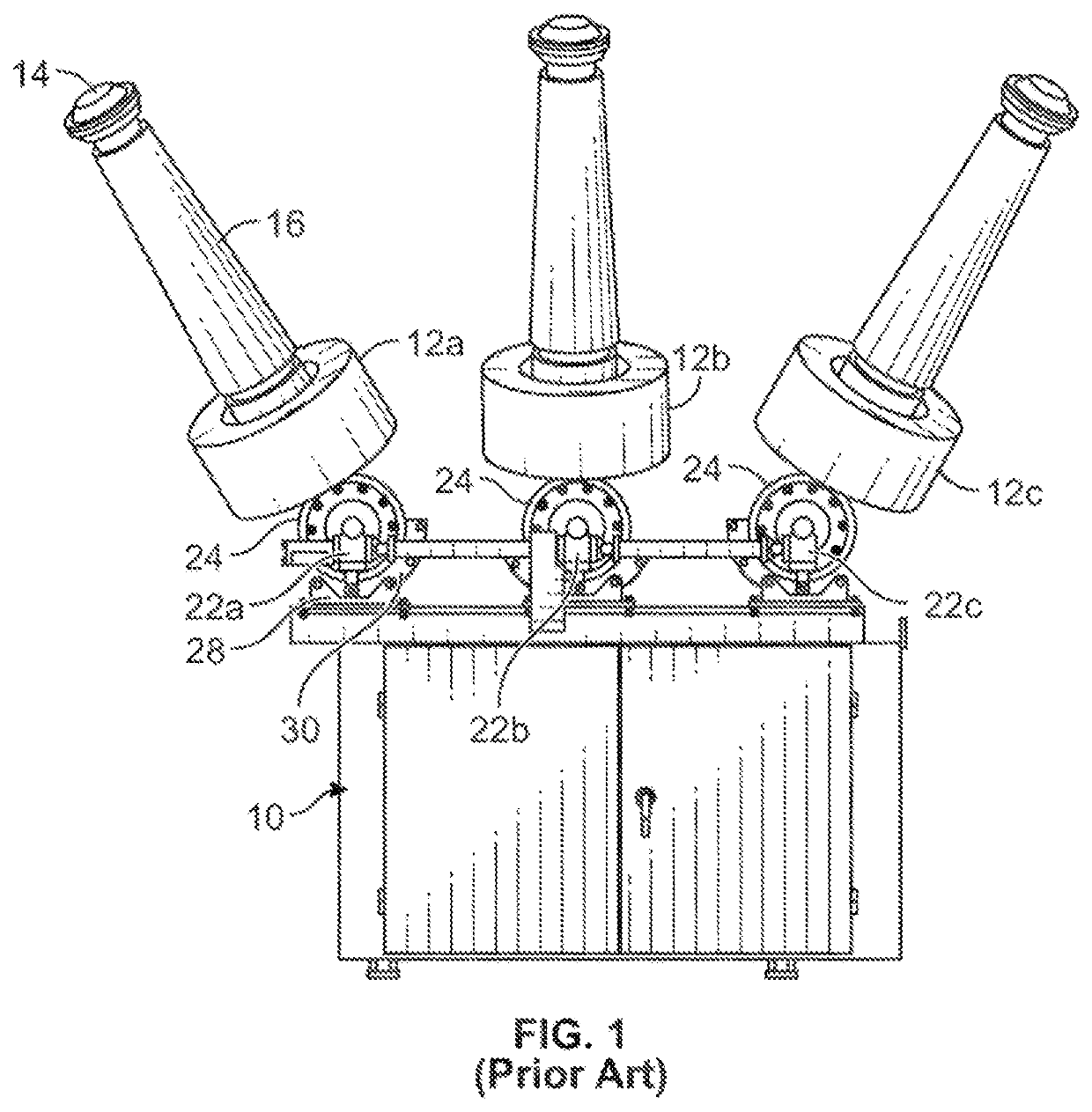
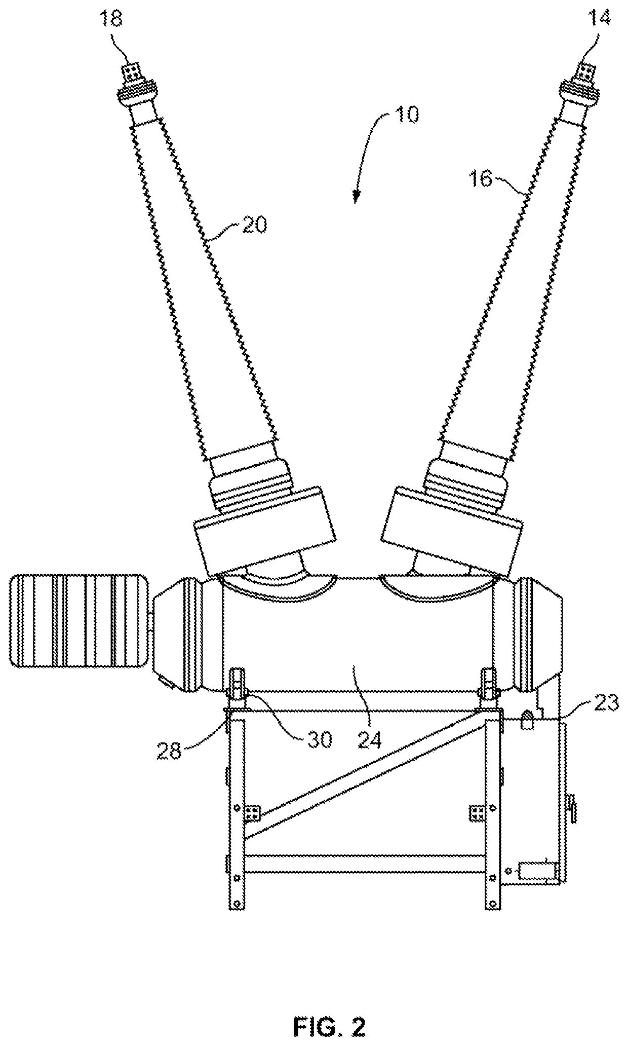
[0018]For purposes of illustration, FIGS. 1 and 2 depict a conventional dead tank circuit breaker, generally indicated at 10. According to the illustrated example, the circuit breaker 10 is a three-phase circuit breaker, and thus includes three pole assemblies including outer pole assemblies 12a and 12c and a central pole assembly 12b. Each pole ...


PUM


Abstract

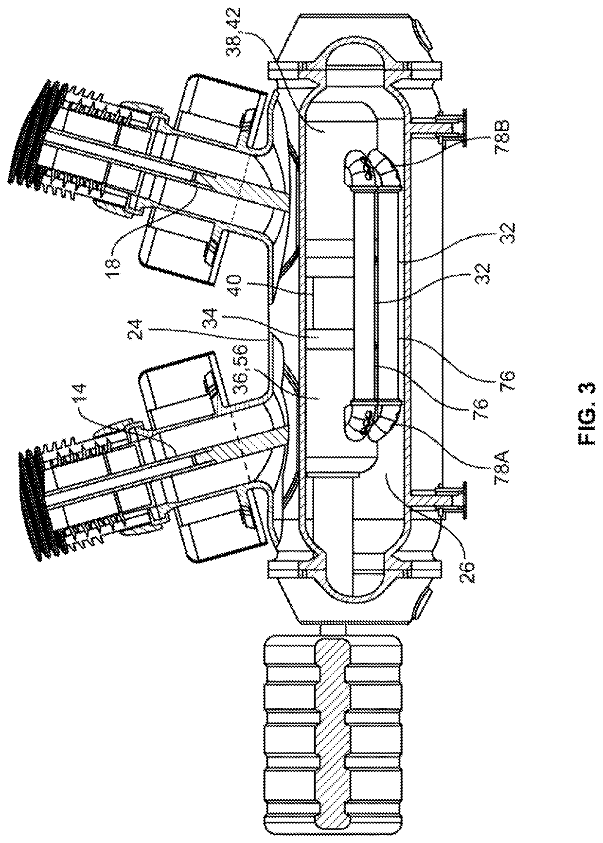
A circuit breaker having at least one capacitor assembly connected in parallel across a contact of the circuit breaker. The capacitor assembly can be housed with the contact within a sealed enclosure of the circuit breaker. The enclosure can be configured to house an insulating medium that is configured to reduce or quench an arc(s) that may form at least when the contact of the circuit breaker is displaced from a closed position to an open position. The capacitor assembly, which includes a transient recovery voltage (TRV) capacitor, can be configured to delay terminal fault and short line fault TRV and the rate of rise of the initial TRV (ITRV) that can appear across the open contact of the circuit breaker.

Description

BACKGROUND[0001]Embodiments of the present invention generally relate to circuit breakers. More particularly, but not exclusively, embodiments of the present invention relate to circuit breakers having internal transient recovery voltage (TRV) capacitor assemblies that are coupled in parallel across the contacts of a circuit breaker.[0002]Various types of circuit breakers used to selectively open and close electrical connections utilize a sealed enclosure or tank that is filled with a liquid or gaseous dielectric insulating medium, including, for example, sulfur hexafluoride (SF6), among other insulating gases and liquids. The dielectric insulating medium within the sealed enclosure can be used in at least an attempt to reduce and / or quench arcing, as well as prevent the flow of electrical current from electrically active parts and at least the enclosure, that can be associated at least with the opening of a contact of the circuit breaker. Moreover, such dielectric insulating medium...

Claims


Application Information

Patent Timeline
IPC IPC(8): H01H33/16H01H9/30
CPCH01H33/165H01H9/30H01H33/16H01H33/70H01H9/42
Inventor SHINDE, SUSHIL A.KURINKO, CARL R.CUPPETT, MATTHEW D.VLADUCHICK, PAUL JASONDAEHLER, CHRISTIANHOBURN, THOMAS E.
Owner HITACHI ENERGY SWITZERLAND AG
Why Eureka
Eureka Blog
Learn More