Safety valve for an automated milker unit backflushing and teat dip applicator system
- Summary
- Abstract
- Description
- Claims
- Application Information
AI Technical Summary
Benefits of technology
Problems solved by technology
Method used
Image

Examples
Embodiment Construction
[0167]The milker unit safety valve 60 is placed at or near the downstream end of the milker unit 40, milk remaining in the long milk tube will not be flushed.
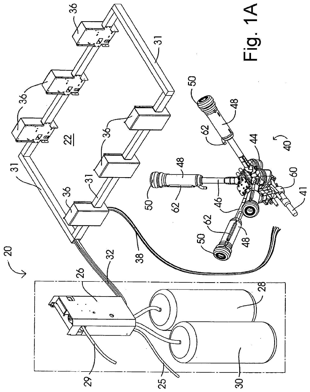
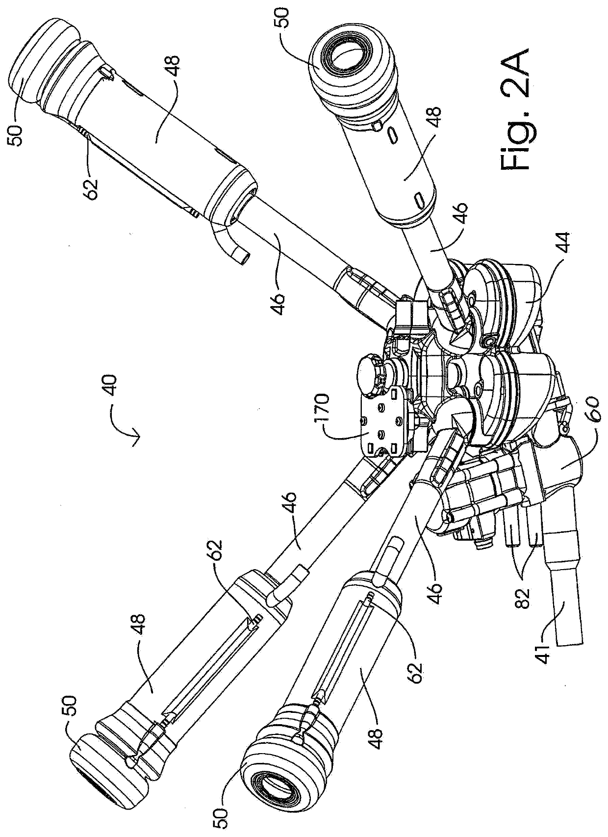
In new milker units 40, the safety valve 60 can be joined to or molded integrally with the milker unit collection bowl so that the backflushing operation flushes out the milker unit 40 including the collection bowl 44, the short milk tubes 46, and the liners 50. (FIGS. 2A, 2B.) Further, a system 20 installed with only a backflushing function can later have an automatic teat dipping feature added, as described in more detail below.
[0168]Short milk tubes 46 are also flushed and they can be of any design because none of the system 20 components connects to or passes through the short milk tubes 46. Nonetheless, the backflushing operation begins downstream from the short milk tubes 46, so any milk or other material in the short milk tubes 46 will be cleaned out in the backflushing operation.
[0169]The safety valve 60 is depicted sep...
PUM
 Abstract
Description
Claims
Application Information
 - Generate Ideas
- Intellectual Property
- Life Sciences
- Materials
- Tech Scout
- Unparalleled Data Quality
- Higher Quality Content
- 60% Fewer Hallucinations
Browse by: Latest US Patents, China's latest patents, Technical Efficacy Thesaurus, Application Domain, Technology Topic, Popular Technical Reports.
© 2025 PatSnap. All rights reserved.Legal|Privacy policy|Modern Slavery Act Transparency Statement|Sitemap|About US| Contact US: help@patsnap.com