Payload deployment tools and methods of using same

Pending Publication Date: 2022-04-14
THOMASON JOHN TYLER
View PDF5 Cites 0 Cited by
  • Summary
  • Abstract
  • Description
  • Claims
  • Application Information

AI Technical Summary

Benefits of technology

The patent provides tools that help energy companies and site operators better understand the features of reservoir rock. These tools are easy to use, cost-effective, and do not leave any harmful chemicals behind. They can also be used to test the productivity of different stages of a hydrocarbon well.

Problems solved by technology

Achieving such an understanding is of great importance, as rock heterogeneity is highly variable and has the potential to negatively affect the performance of a well.
Unfortunately, typical survey and scientific methods have proven ill-suited to obtain an adequate understanding of reservoir heterogeneity, as rock layers are deposited over millions of years with lithologic and structural variations that are difficult to detect using low-resolution 3D seismic or scanning gamma ray tools.
For example, hydrocarbon extraction from low-pressure portions of reservoir rock in a parent well may be negatively affected by fracturing of a child well (i.e., a well formed after the parent well) drilled nearby, as high-pressure fracturing fluid injected into the child well may propagate across the reservoir rock to low-pressure portions of the parent well.
This hydraulic communication hinders stimulation of the child well and floods the parent well with fracturing fluid, thereby degrading performance of both wells.
While this process allows well site operators to gain valuable information concerning flow at individual fracturing stages, the limited availability of unique and suitable chemical markers (approximately 60 currently available) limits its effectiveness, especially in view of recent advances in fracturing technologies that permit an ever increasing number of stages per well.
The process is further limited, as the chemical markers tend to leach into and contaminate adjacent wells, thereby limiting the ability of operators from using the same chemical markers to measure flow characteristics of different wells at the same fracturing site.

Method used


Image

  • Payload deployment tools and methods of using same
  • Payload deployment tools and methods of using same
  • Payload deployment tools and methods of using same

Examples


Embodiment Construction

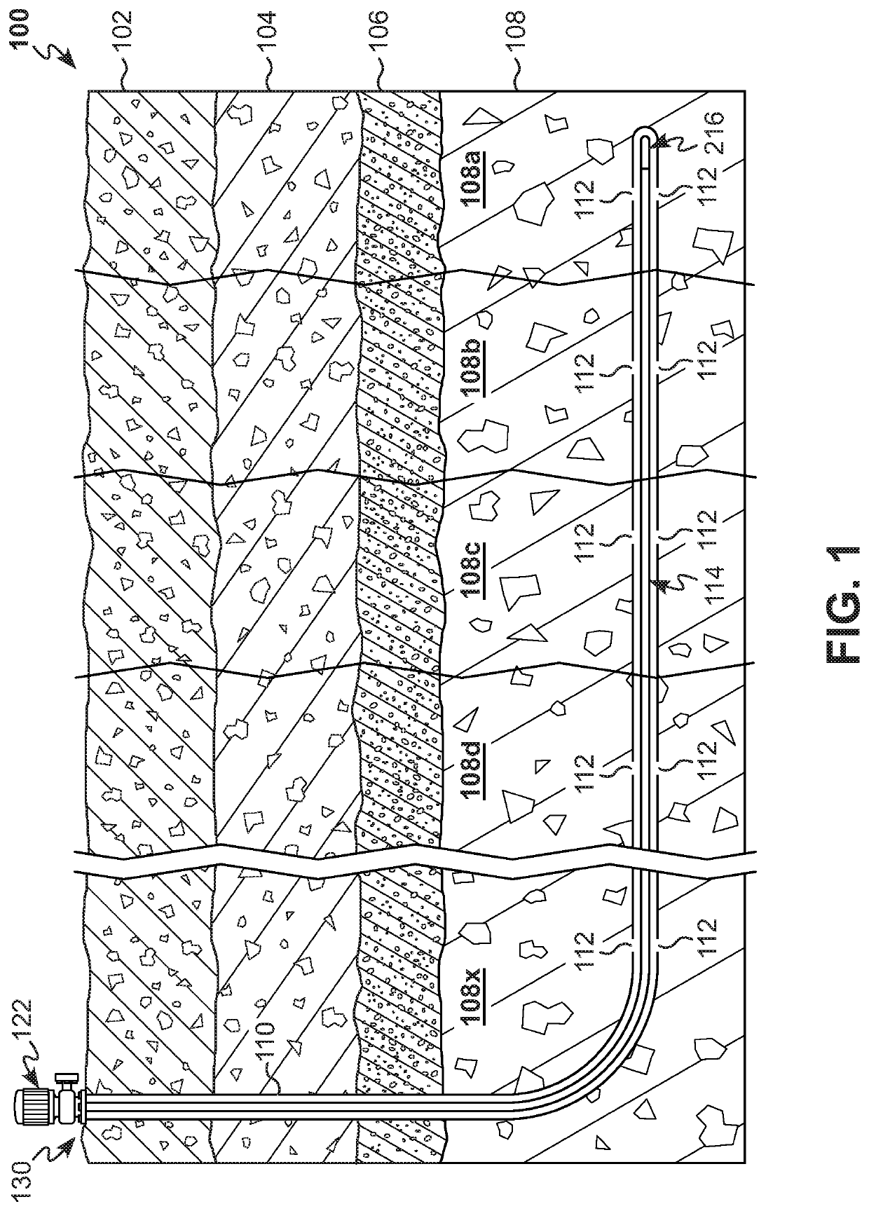
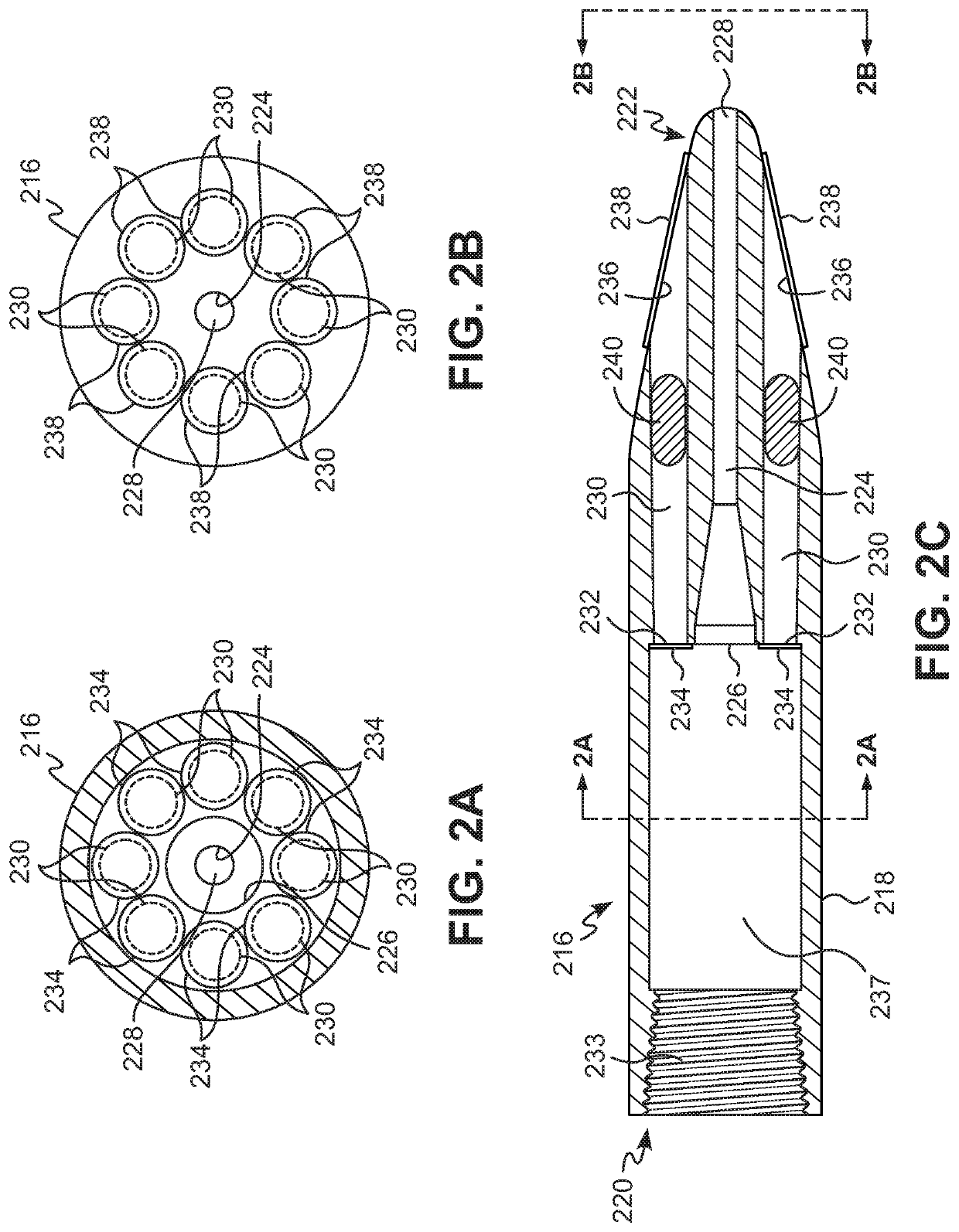
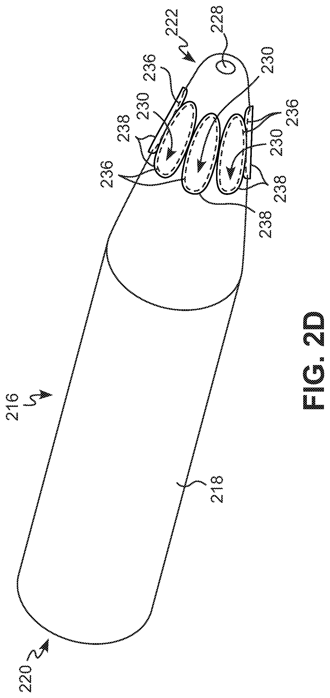
[0034]Reference will now be made in detail to the various exemplary embodiments of the subject disclosure illustrated in the accompanying drawings. Wherever possible, the same or like reference numbers will be used throughout the drawings to refer to the same or like features. It should be noted that the drawings are in simplified form and are not drawn to precise scale. Certain terminology is used in the following description for convenience only and is not limiting. Directional terms such as top, bottom, left, right, above, below and diagonal, are used with respect to the accompanying drawings. The term “distal” shall mean away from the center of a body. The term “proximal” shall mean closer towards the center of a body and / or away from the “distal” end. The words “inwardly” and “outwardly” refer to directions toward and away from, respectively, the geometric center of the identified element and designated parts thereof. Such directional terms used in conjunction with the followin...


PUM


Abstract

A payload deployment tool is provided. The tool includes a housing having a coupler configured to couple to a fluid delivery conduit; a pressure chamber in communication with the coupler; a plurality of payload chambers in communication with the pressure chamber, each of the payload chambers having an upstream opening and a downstream opening; and a plurality of upstream pressure-rupturable seals respectively covering the upstream openings.

Description

[0001]The subject disclosure relates generally to tools and methods for use in crude oil and natural gas production wells, and more specifically, to payload deployment tools and methods for selectively discharging desired payloads into oil and gas wells.BACKGROUND OF THE DISCLOSURE[0002]Energy companies, such as fracturing companies, strive to achieve an understanding of the heterogeneity of targeted reservoir rock both vertically and horizontally, including, for example, a variation of rock properties along a wellbore. Achieving such an understanding is of great importance, as rock heterogeneity is highly variable and has the potential to negatively affect the performance of a well.[0003]Unfortunately, typical survey and scientific methods have proven ill-suited to obtain an adequate understanding of reservoir heterogeneity, as rock layers are deposited over millions of years with lithologic and structural variations that are difficult to detect using low-resolution 3D seismic or s...

Claims


Application Information

Patent Timeline
IPC IPC(8): E21B34/06E21B47/11
CPCE21B34/063E21B47/11E21B23/04E21B27/02E21B27/00
Inventor THOMASON, JOHN TYLER
Owner THOMASON JOHN TYLER
Why Eureka
Try Eureka