Assembly and method for sealing a bundle of wires

a bundle and wire technology, applied in the direction of insulated conductors, cables, conductors, etc., can solve the problems of increasing production time and cost, increasing the damage of the wire insulation layer, and the problem of existing sealing members, so as to facilitate the thermal energy distribution of applied heat, reduce the viscosity of the sealant material, and soften the sealant material.

Active Publication Date: 2022-04-14
TE CONNECTIVITY CORP
View PDF7 Cites 0 Cited by
  • Summary
  • Abstract
  • Description
  • Claims
  • Application Information

AI Technical Summary

Benefits of technology

[0006]In one aspect, a sealing assembly for sealing a bundle of wires includes a first sheet formed of a sealant material, a second sheet disposed above the first sheet, and a cover to be disposed around the first sheet and the second sheet. The second sheet includes a thermally conductive material. When the bundle of wires is overlaid on the assembly in a first direction, and the assembly is wrapped in a second direction that is generally perpendicular to the first direction to thereby surround the wires, the second sheet facilitates thermal energy distribution of applied heat throughout the assembly to thereby soften the sealant material and thereby lower viscosity of the sealant material to a point at which the sealant material flows and fills voids between the bundle of wires, and the cover maintains the sealant material between the wires.
[0007]In a second aspect, an integrated sealing assembly for sealing a bundle of wires includes a lower portion that defines a generally planar shape, a plurality of vertical members extending from the lower portion having a space there between for placement of one or more wires in a first direction, and a thermally conductive material embedded within the lower portion. The integrated sealing assembly is formed from a sealant material. When one or more wires are arranged within the space between the plurality of vertical members in the first direction and the integrated sealing assembly is wrapped in a second direction that is generally perpendicular to the first direction to thereby surround the wires, the thermally conductive material of the integrated sealing assembly facilitates thermal energy distribution of applied heat throughout the assembly to thereby lower a viscosity of the sealant material to a point at which the sealant material of the integrated sealing assembly fills voids between the one or more wires.
[0008]In a third aspect, a method for sealing a bundle of wires includes providing a sealing assembly. The sealing assembly includes a first sheet formed of a sealant material, a second sheet disposed above the first sheet, and a third sheet disposed above the second sheet formed of the sealant material. The second sheet includes a thermally conductive material. The bundle of wires is overlaid on the third sheet in a first direction. The sealing assembly and bundle of wires are wrapped together in a second direction that is generally perpendicular to the first direction. Heat is applied to the wrapped assembly. The second sheet facilitates thermal energy distribution of the applied heat throughout the assembly to thereby uniformly melt the sealant material and thereby fill voids between the wires.

Problems solved by technology

For example, there is a possibility of overheating due to electromagnetic coupling between the wires and the magnetic field which may occur when the wires are twisted.
This may result in wire insulation layer damage.
The magnetic flakes of specific composition and configuration may need to be oriented in a particular way when inserted into the sealant, which can increase production time and cost.
Other problems with existing sealing members will become apparent in view of the disclosure below.

Method used


Image

  • Assembly and method for sealing a bundle of wires
  • Assembly and method for sealing a bundle of wires
  • Assembly and method for sealing a bundle of wires

Examples


Embodiment Construction

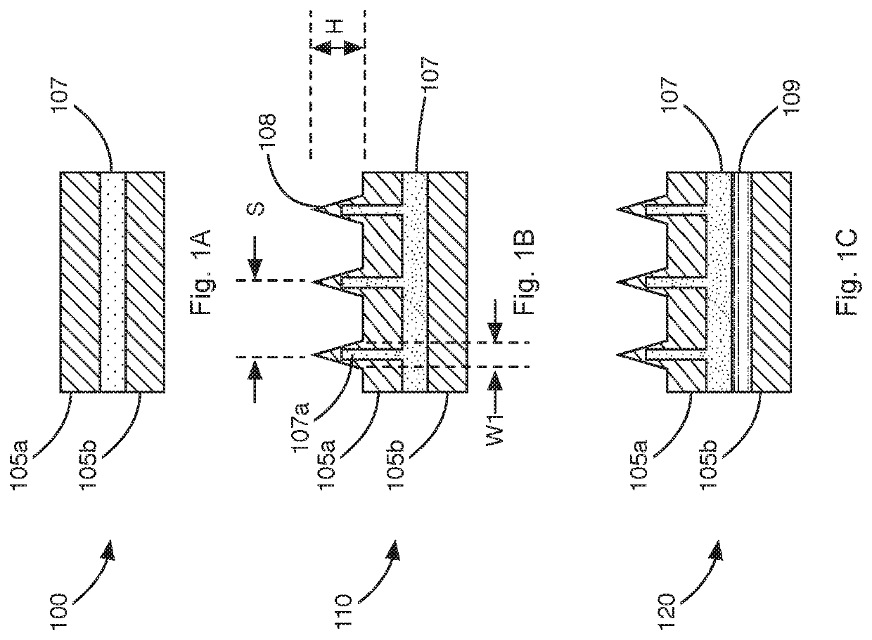
[0027]FIG. 1A illustrates a cross-section of an exemplary sealing assembly 100 for sealing a bundle of wires. The sealing assembly 100 includes top and bottom layers 105a,105b or sheets formed from a sealant material. The middle layer 107 or sheet may include a thermally conductive material and a sealant material, which may be the same or different than the sealant material used for forming the top and bottom layers 105a,105b. The thermally conductive material helps to promote more uniform and faster distribution of heat through the sealing assembly 100.

[0028]The top, middle and bottom layers 105a, 107, and 105b may be formed from one of several sealant materials described below. In an exemplary implementation, the thickness of the top and bottom layers 105a,105b may be between about 0.5-2 mm. The thickness of the two layers 105a,105b may be the same or different.

[0029]The middle layer 107 may include a thermally conductive material embedded within the sealant material from which th...


PUM

PropertyMeasurementUnit
temperatureaaaaaaaaaa
viscosityaaaaaaaaaa
temperatureaaaaaaaaaa

Abstract

A sealing assembly for sealing a bundle of wires includes a first sheet formed of a sealant material, a second sheet disposed above the first sheet, and a third sheet disposed above the second sheet formed of the sealant material. The second sheet includes a thermally conductive material. When the bundle of wires is overlaid on the assembly in a first direction, and the assembly is wrapped in a second direction that is generally perpendicular to the first to thereby surround the wires, the second sheet facilitates enhanced thermal energy distribution of applied heat throughout the assembly to thereby more uniformly melt the sealant material and thereby fill voids between the wires.

Description

BACKGROUNDField[0001]The present invention relates generally to wire assemblies. More specifically, the present invention relates to an assembly and method for sealing a bundle of wires.Description of Related Art[0002]Sealing of wire bundles is typically required in applications where large numbers of wires pass through a wall that separates regions having different environmental conditions. For example, in automobiles, wires from various sensors, controllers and the like may pass from the engine compartment, through an opening in the firewall, to a computer located in the cabin. In the region where the wires pass through the opening, the wires may be surrounded by a sealing member. The sealing member is configured to completely encapsulate the wires and ideally fill in voids between the wires to prevent moisture from traveling along the wires into the cabin. The sealing member or members are also configured to provide a watertight fit with the opening in the firewall. The sealant a...

Claims


Application Information

Patent Timeline
Patent Type & Authority Applications(United States)
IPC IPC(8): H02G3/04B60R16/02H01B7/285H02G15/013H01B7/28H01B7/00B29C35/02B29C35/08B29C63/00B29C63/06H01B13/00
CPCH02G3/0418B60R16/0215H01B7/285H02G15/013H01B7/28H01B7/0045B29D99/0053B29C35/0805B29C63/0065B29C63/06H01B13/0036B29C2035/0811B29C2035/0822B29C35/02B29K2105/256B29L2031/3462
Inventor DAGA, VIJAYDAS, JAYDIPBHARADWAJ, KAVITHAGAO, TINGPOLOSKY, QUENTIN FRANCISCERVANTES, HENRY PAUL S.
Owner TE CONNECTIVITY CORP
Why Eureka
Try Eureka