
System and method for detection of mobile device fault conditions

a mobile device and fault technology, applied in the field of systems and methods for detecting fault conditions in mobile devices, to achieve the effect of improving the defect detection performan

Inactive Publication Date: 2022-04-21
BLANCCO TECH GRP IP OY
View PDF1 Cites 3 Cited by
  • Summary
  • Abstract
  • Description
  • Claims
  • Application Information

AI Technical Summary

Benefits of technology

The present invention provides a method for training a neural network to detect defects in captured images of mobile devices. The training data may be stored in a database to allow for additional training and improvement of the defect detection performance. The training data may also be manually modified to identify defects and areas erroneously identified as containing a defect. The pre-trained neural network can be re-trained with the augmented training data at any desired time or on a periodic basis. The technical effect of the invention is to provide a more robust and accurate method for detecting defects in mobile devices.

Problems solved by technology

For example, the software may be installed on the device when purchased or downloaded after the device is purchased, or even after the device damaged or otherwise becomes faulty.

Method used


Image

  • System and method for detection of mobile device fault conditions
  • System and method for detection of mobile device fault conditions
  • System and method for detection of mobile device fault conditions

Examples


embodiment 100

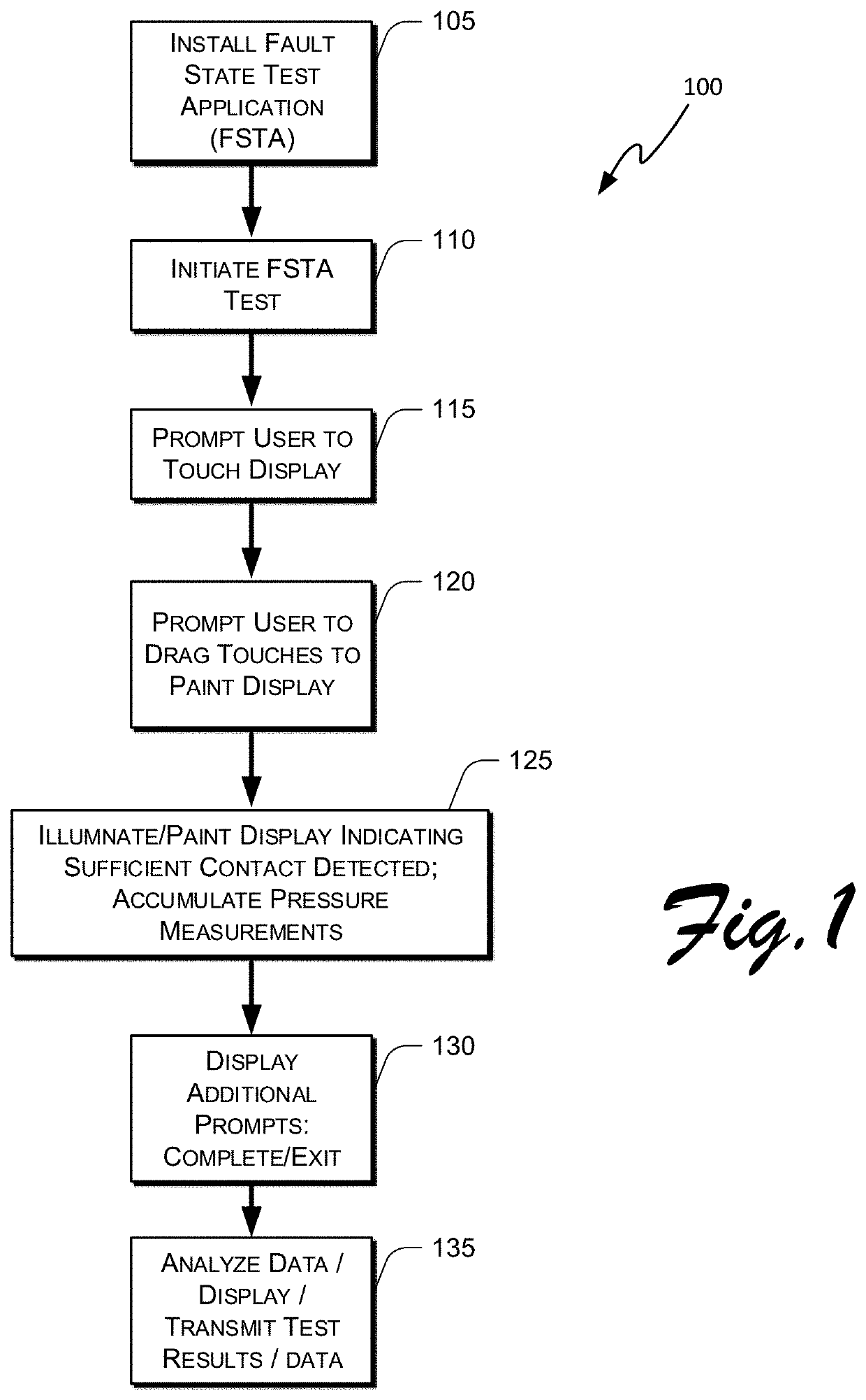
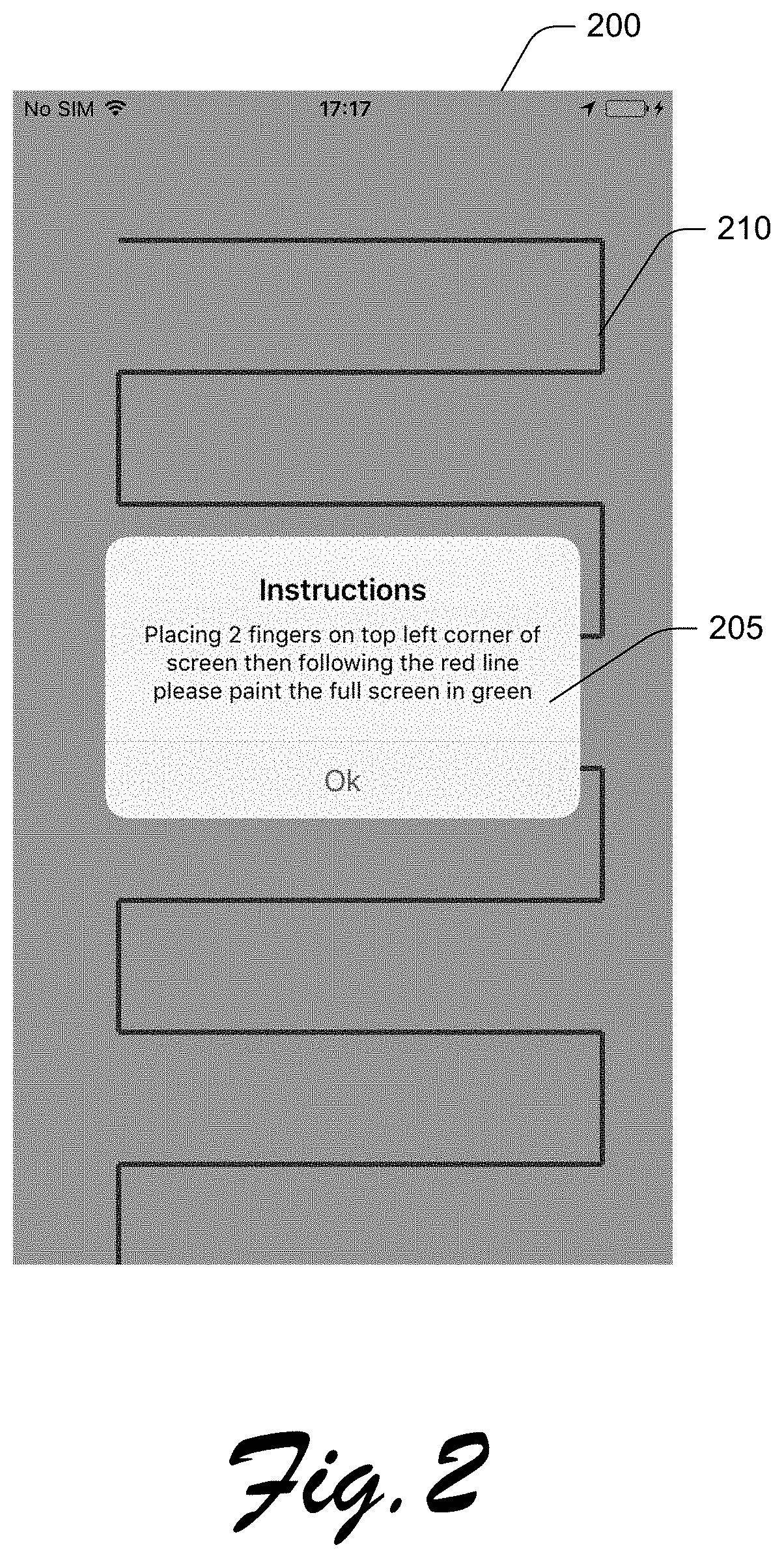
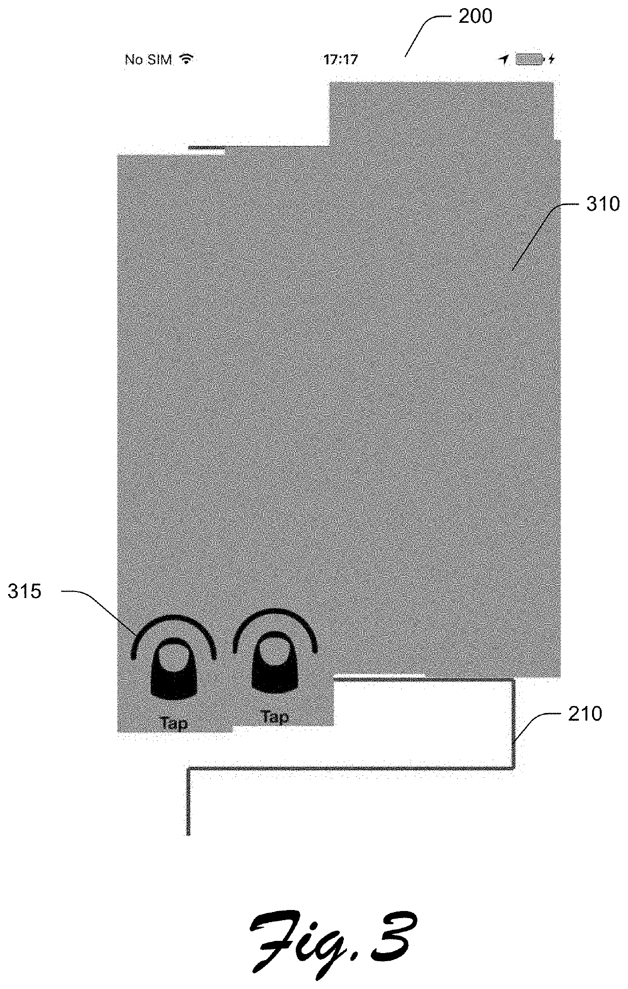
[0089]In one preferred embodiment 100 shown in FIG. 1, the user executes 110 the FSTA app (after installation 105, if the app had not already been installed), and the user is prompted 115 by the FSTA to touch two fingers to the display, either left finger first then right finger, or right finger first then left finger, or both approximately simultaneously, as may be desired in obtaining the most appropriate pressure readings. The FSTA detects the pressure readings for each touch zone, and the test continues by prompting 120 the user to drag the two fingers across the screen to “paint” the screen, as FSTA displays illumination 125 on the display when it has detected touches of sufficient measured pressure in the areas. The user may be prompted to simply drag both fingers in any direction until the entire screen is “painted” by the FSTA app (after it detects all areas of the screen have received the appropriate drag touches) or preferably, to follow a particular path in “painting” the...

embodiment 700

[0095]In one preferred embodiment 700 shown in FIG. 7, the user executes 710 the FSTA app (after installation 705, if the app had not already been installed), and the user is prompted 715 by the FSTA to touch (see also FIG. 9, 905) the display 200, with a pattern presented to the user (see also FIG. 9, 910) that will need to be filled in from discrete finger touches, as prompted 720 by the FSTA. In this embodiment, the FSTA will measure and accumulate magnetometer readings as each prompted area 905 is pressed by the user, and if sufficient pressure is applied, each individual area of the display 200 is “painted”725 to provide user feedback (see FIG. 10, showing partially painted section 1005, and unpainted part of pattern 910). While painting the display, the FSTA detects and accumulates the magnetometer readings for each touched zone 725, and the test proceeds until a predetermined amount of the display 200 has been painted. In various embodiments, substantially all of the screen w...


PUM

PropertyMeasurementUnit
aspect ratiosaaaaaaaaaa
sizeaaaaaaaaaa
defect analysisaaaaaaaaaa

Abstract

There is presented a system and method for detecting mobile device fault conditions, including detecting fault conditions by software operating on the mobile device. In one embodiment, the present invention provides for systems and methods for using a neural network to detect, from an image of the device, that the mobile device has a defect, for instance a cracked or scratched screen. Systems and methods also provide for, reporting the defect status of the device, working or not, so that appropriate action may be taken by a third party.

Description

CROSS REFERENCE TO RELATED APPLICATIONS[0001]This application is a divisional application of and claims priority to and full benefit of U.S. patent application Ser. No. 15 / 899,339, filed Feb. 19, 2018, titled, “System and Method For Detection Of Mobile Device Fault Conditions,” which claims full benefit of and priority to U.S. provisional patent application No. 62 / 329,159 filed Apr. 28, 2016 titled, “System and Method For Detection Of Mobile Device Fault Conditions,” and claims full benefit of and priority to U.S. provisional patent application No. 62 / 464,366 filed Feb. 27, 2017 titled, “System And Method For Monitoring and Tracking Device Health”, and claims full benefit of and priority to U.S. provisional patent application No. 62 / 463,725 filed Feb. 26, 2017 titled, “System and Method For Detection Of Display Defects”; and further, U.S. patent application Ser. No. 15 / 899,339 identified above is a continuation-in-part of and claims full benefit of U.S. non-provisional application S...

Claims


Application Information

Patent Timeline
Patent Type & Authority Applications(United States)
IPC IPC(8): G06T7/00G01N21/88G01N21/95G06T7/80H04N5/235H04N5/262G06N3/08H04N5/232H04N7/18G06N3/04G06T7/13G06V10/42
CPCG06T7/001G01N21/958G01N21/95G06T7/80H04N5/2353H04N5/2354H04N5/2628G06N3/08H04N5/23222H04N7/18G06N3/0454G06T7/0004G06T7/13G06N3/084G06V10/42G01N2021/8858G01N2021/9513G01N2021/8893G06T2207/30121G06T2207/20084G06T2207/10024G01N21/8851G06V10/40G06V10/245G06V10/25G06T2207/20081G01N2021/8883G01N2021/8887H04N23/64H04N23/73H04N23/74H04N23/76G06N3/045G01N2201/0221G06T2207/30244G01N2021/8854G06T7/0002G06Q10/30
Inventor FITZGERALD, WILLIAMO'SHAUGHNESSY, DONALKELLY, DONIEO'SULLIVAN, PAULO'CALLAGHAN, LIAMDONOVAN, JAMESHALLINAN, SHANEMCGRORY, CHARLIEMORGAN, WAYNECHITTURI, UDAYCONWAY, PATRICKMOLLAGHAN, JOHNSUTTON, KEVIN
Owner BLANCCO TECH GRP IP OY
Learn More