
Small lens system for tof

Pending Publication Date: 2022-04-28
SEKONIX
View PDF0 Cites 0 Cited by
  • Summary
  • Abstract
  • Description
  • Claims
  • Application Information

AI Technical Summary

Benefits of technology

The present invention is a small lens system for ToF that consists of four lenses. The thickness of each lens is set, the refractive power and shape of the second lens are adjusted, and an f-number is reduced. This results in excellent lens sensitivity, which enables accurate information gathering, and alleviates tolerance sensitivity, improving the performance and productivity of the lenses. In summary, the goal of the invention is to provide a high-quality small lens system for ToF applications.

Problems solved by technology

In addition, the performance and productivity of the lenses must be excellent, and therefore the lenses must be insensitive to tolerance.
However, light may not be properly reflected or may be transmitted depending on a photographing environment or the surface texture or color of an object to be photographed.
In this case, it is difficult to acquire accurate depth information.
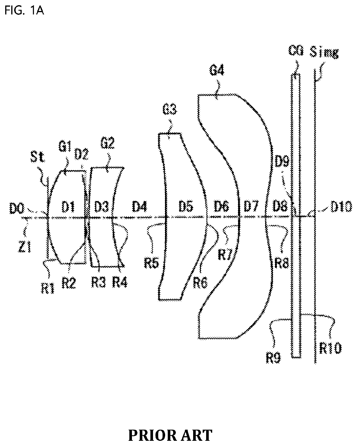
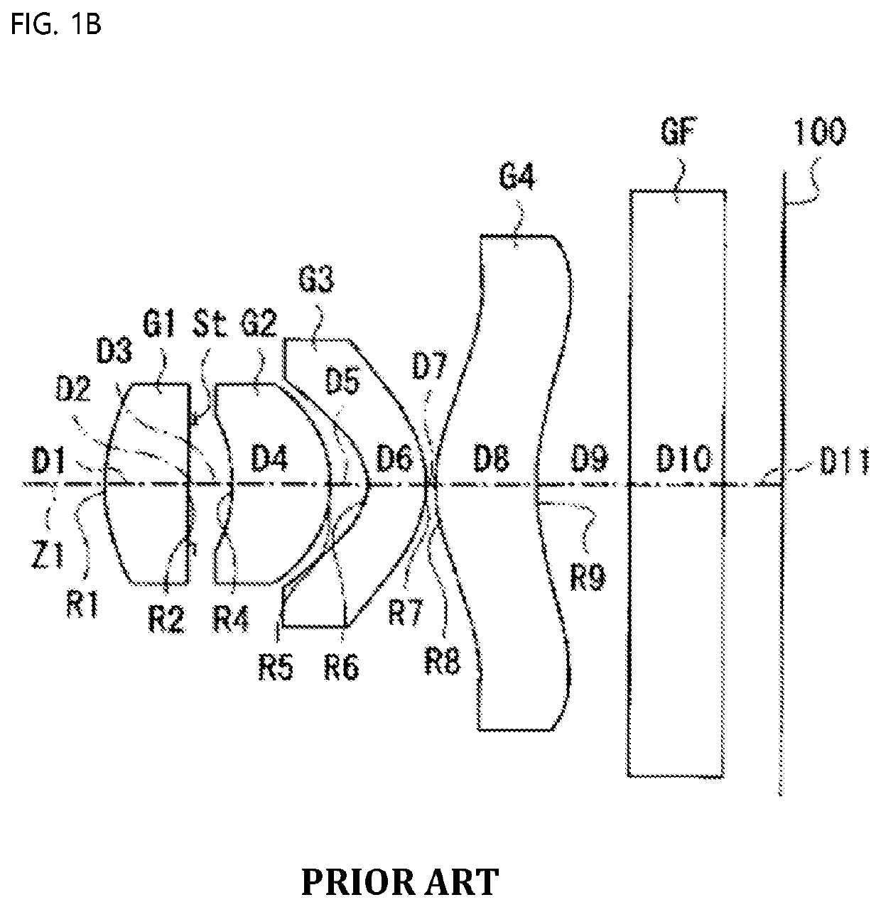
As described above, the conventional technologies have problems in that the f-number is relatively large, and the lenses are sensitive to tolerance, whereby it is difficult to provide accurate 3D information about an object when being applied to a TOF camera, and the performance and productivity of the lenses are low.

Method used


Image

  • Small lens system for tof
  • Small lens system for tof
  • Small lens system for tof

Examples


first embodiment

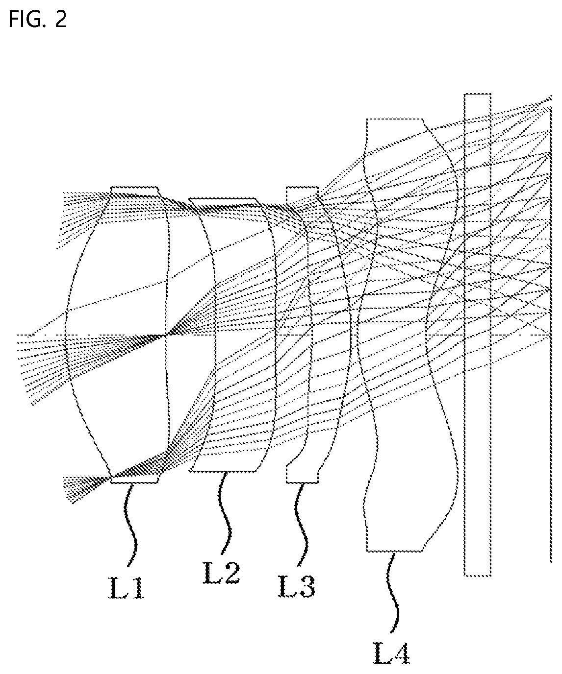
[0060]FIG. 2 is a view showing a first embodiment of the small lens system for TOF according to the present invention.

[0061]As shown, in the first embodiment of the small lens system for TOF according to the present invention, a first lens L1, a second lens L2, a third lens L3, and a fourth lens L4 are sequentially arranged from an object along an optical axis.

[0062]Table 1 below shows numerical data of the lenses constituting the lens system according to the first embodiment of the present invention.

TABLE 1SurfaceRDYNdVd (Surface(Radius ofTHI(Refractive(Abbenumber)curvature)(Thickness)index)number)OBJECTINFINITYINFINITY11.8340.821.64119.5STOP6.3610.423INFINITY0.491.59425.94INFINITY0.305−2.0250.321.64119.56−2.3320.0571.0390.571.59425.981.1540.329INFINITY0.211.50864.210INFINITY0.88IMAGEINFINITY0.03

[0063]As shown in FIG. 2, the first lens L1, the second lens L2, the third lens L3, and the fourth lens L4 are sequentially arranged from the object. On the assumption that an optical-axis ...

second embodiment

[0074]FIG. 4 is a view showing a second embodiment of the small lens system for TOF according to the present invention.

[0075]As shown, in the first embodiment of the small lens system for TOF according to the present invention, a first lens L1, a second lens L2, a third lens L3, and a fourth lens L4 are sequentially arranged from an object along an optical axis.

[0076]Table 3 below shows numerical data of the lenses constituting the lens system according to the second embodiment of the present invention.

TABLE 3SurfaceRDYNdVd (Surface(Radius ofTHI(Refractive(Abbenumber)curvature)(Thickness)index)number)OBJECTINFINITYINFINITY11.8410.851.64119.5STOP6.1000.30320.5050.491.59425.9424.1110.395−2.6650.381.64119.56−2.4510.0571.1210.521.59425.981.1310.329INFINITY0.211.50864.210INFINITY1.00IMAGEINFINITY0.03

[0077]As shown in FIG. 4, the first lens L1, the second lens L2, the third lens L3, and the fourth lens L4 are sequentially arranged from the object. On the assumption that an optical-axis di...

third embodiment

[0088]FIG. 6 is a view showing a third embodiment of the small lens system for TOF according to the present invention.

[0089]As shown, in the third embodiment of the small lens system for TOF according to the present invention, a first lens L1, a second lens L2, a third lens L3, and a fourth lens L4 are sequentially arranged from an object along an optical axis.

[0090]Table 5 below shows numerical data of the lenses constituting the lens system according to the third embodiment of the present invention.

TABLE 5SurfaceRDYNdVd (Surface(Radius ofTHI(Refractive(Abbenumber)curvature)(Thickness)index)number)OBJECTINFINITYINFINITY11.8140.851.64119.5STOP6.1920.293−443.8790.501.59425.94−631.5410.375−2.4640.371.64119.56−2.4470.0571.0850.521.59425.981.1320.339INFINITY0.211.50864.210INFINITY1.00IMAGEINFINITY0.03

[0091]As shown in FIG. 6, the first lens L1, the second lens L2, the third lens L3, and the fourth lens L4 are sequentially arranged from the object. On the assumption that an optical-axis ...


PUM


Abstract

Disclosed is a small lens system including a first lens, a second lens, a third lens, and a fourth lens sequentially arranged from an object along an optical axis, wherein the thickness (ct1) of the first lens, the thickness (ct3) of the second lens, the thickness (ct5) of the third lens, and the thickness (ct7) of the fourth lens satisfy ct1+ct3>ct5+ct7, ct1>ct3, ct1>ct5, and ct1>ct7, the front surface of the first lens is convex toward the object while the SAG amount of the first lens is increased depending on the height thereof, the refractive power (P2) of the second lens satisfies −0.01<P2<0.01, the front curvature (C3) and the rear curvature (C4) of the second lens satisfy |C3|<0.1 and |C4|<0.1, and the f-number of the lens system is less than 1.4.

Description

CROSS REFERENCE TO RELATED APPLICATION[0001]The present application claims priority to Korean Patent Application No. 10-2020-0137367, filed Oct. 22, 2020, the entire contents of which is incorporated herein for all purposes by this reference.BACKGROUND OF THE INVENTIONField of the Invention[0002]The present invention relates to a small lens system, and more particularly to a small lens system for TOF configured such that lens sensitivity is excellent, whereby it is possible to provide accurate information, and tolerance sensitivity is alleviated, whereby the performance and productivity of lenses are improved.Description of the Related Art[0003]With recent increasing demand for high-quality, high-performance, miniaturized, and lightweight electronic equipment having a camera function, research to realize the same through improvement in performance of a subminiature lens optical system has been conducted.[0004]For a small lens system mounted in such miniaturized and lightweight elect...

Claims


Application Information

Patent Timeline
IPC IPC(8): G02B13/00G02B9/34
CPCG02B13/004G02B9/34G02B3/0087G02B3/04G02B1/041G02B2003/0093
Inventor NOH, KI YOUNCHOI, SOON CHEOLKIM, SUNG NYUNBAE, SEONG JUN
Owner SEKONIX
Learn More