Battery cell and battery module

a battery cell and battery module technology, applied in the direction of batteries, cell components, sustainable manufacturing/processing, etc., can solve the problems of easy loosening of components and difficult heat sealing of contact layers, and achieve the effect of suppressing the deterioration of the electrode unit and improving the durability of the battery cell

Active Publication Date: 2022-04-28
HONDA MOTOR CO LTD
View PDF2 Cites 0 Cited by
  • Summary
  • Abstract
  • Description
  • Claims
  • Application Information

AI Technical Summary

Benefits of technology

[0019]According to the present invention, since the housing unit and the first insulator are fixed, a jolt of the electrode unit caused by a jolt of the housing unit can be suppressed by indented shape of the first insulator. Thus, deterioration of the electrode unit is suppressed, thereby durability of the battery cell being improved.

Problems solved by technology

If the housing unit is a thick material such as a metal plate, however, it is not easy to heat-seal the contact layer to fix the external terminal or the like, and thereby components being prone to be loose.

Method used


Image

  • Battery cell and battery module
  • Battery cell and battery module
  • Battery cell and battery module

Examples


first embodiment

[0030]First, a battery cell according to a first embodiment of the present invention will be described with reference to FIGS. 1 to 6.

[0031]Battery Cell

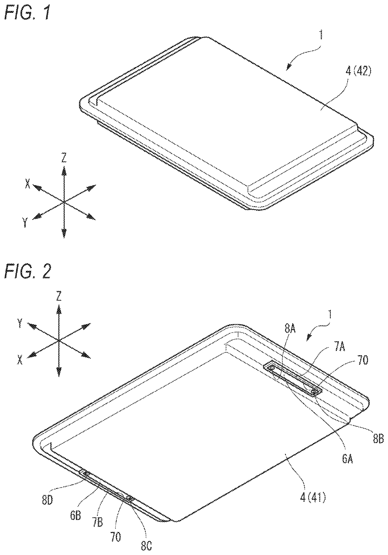
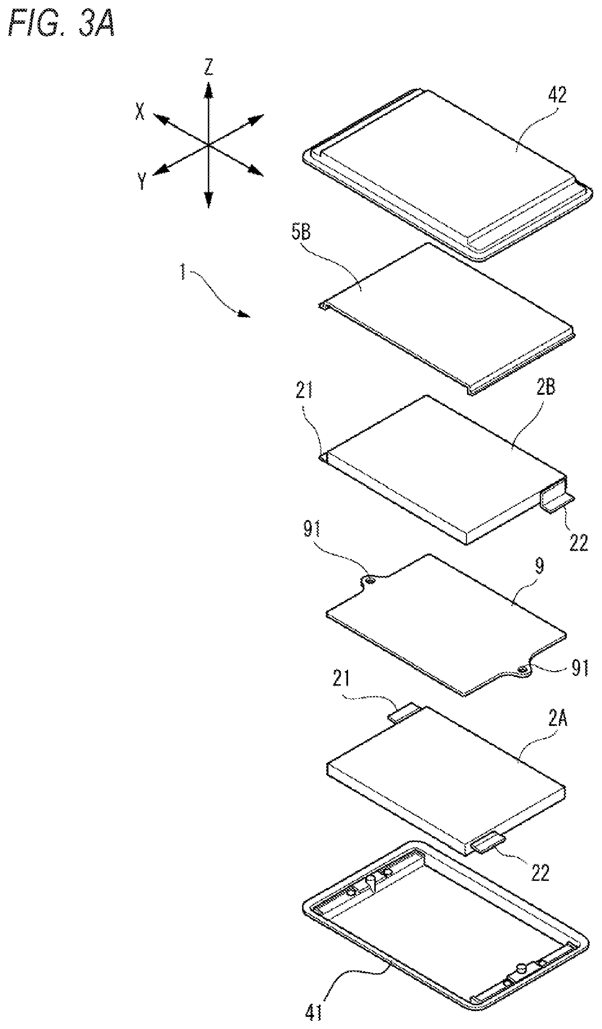
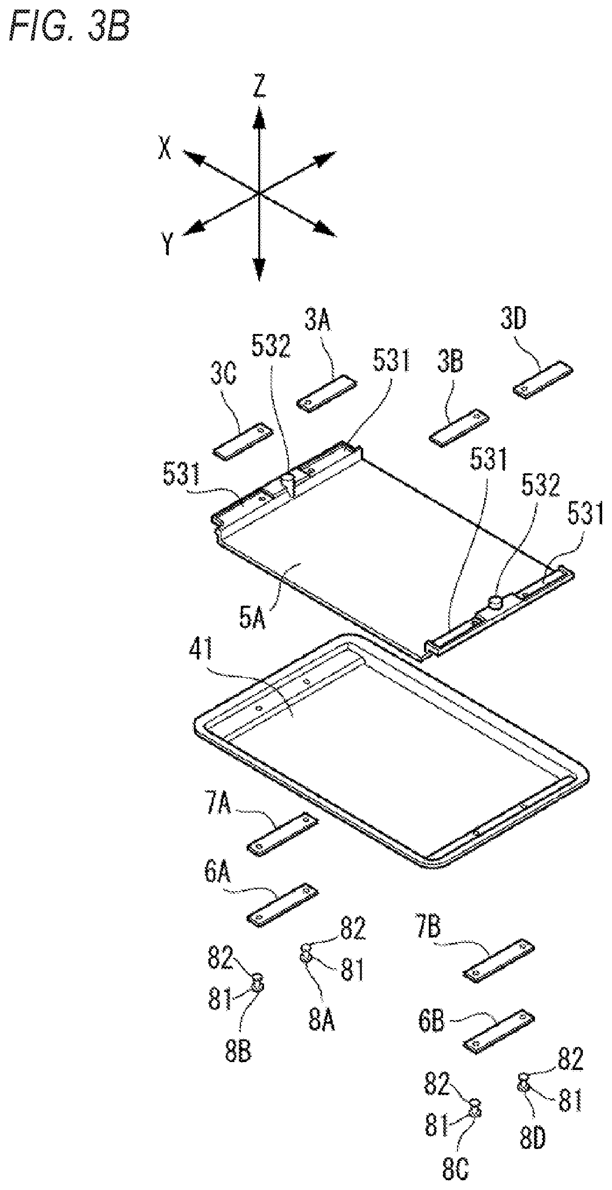
[0032]As shown in FIGS. 1 to 4, a battery cell 1 includes: electrode units 2A and 2B; internal terminals 3A to 3D electrically connected to the electrode units 2A and 2B; a housing unit 4 accommodating the electrode units 2A and 2B and the like; internal insulators 5A and 5B disposed between the electrode unit 2A or 2B and the housing unit 4 and between the internal terminals 3A to 3D and the housing unit 4; external terminals 6A and 6B disposed outside the housing unit 4; external insulators 7A and 7B disposed between the external terminal 6A or 6B and the housing unit 4; and fixing members 8A to 8D. In the battery cell 1 according to the present embodiment, a middle plate 9 is disposed between a pair of the electrode units 2A and 2B in order to accommodate the pair of the electrode units 2A and 2B piled in the Z-direction. The midd...

second embodiment

[0062]Next, a battery cell 1B according to a second embodiment will be described with reference to FIGS. 7 and 8. Configurations similar to the first embodiment are denoted by the same reference numerals as those of the first embodiment, and the description of the first embodiment may be incorporated.

[0063]Battery Cell

[0064]As shown in FIG. 7, the battery cell 1B according to the second embodiment differs from that according to the first embodiment in that: single electrode unit 2A is accommodated, a first housing member 41 to which the internal terminals 3A and 3B and the external terminals 6A and 6B are fixed has flat shape, and external insulators 7A and 7B include engagement portions 71 protruding in the Z-direction.

[0065]A distance between surfaces of the engagement portions 71 formed in the external insulators 7A and 7B facing each other in the X-direction is set to be equal to or slightly wider than a width of an outer surface of the electrode-unit accommodating portion 421 o...


PUM

PropertyMeasurementUnit
thicknessaaaaaaaaaa
heightaaaaaaaaaa
durabilityaaaaaaaaaa

Abstract

A battery cell includes: an electrode unit including a positive electrode, a negative electrode, a current collector, and a separator; a housing unit accommodating the electrode unit; a first insulator disposed inside the housing unit and between the electrode unit and the housing unit, an internal terminal disposed inside the housing unit and electrically connected to the current collector; a second insulator disposed inside the housing unit and between the internal terminal and the housing unit; and an external terminal disposed outside the housing unit. A contact surface of the first insulator with the electrode unit has indented shape. The first insulator is fixed to the housing unit.

Description

CROSS-REFERENCE TO RELATED APPLICATION[0001]This application is based on and claims priority under 35 USC 119 from Japanese Patent Application No. 2020-179917, filed on Oct. 27, 2020, the contents of which are incorporated herein by reference.TECHNICAL FIELD[0002]The present invention relates to a battery cell and a battery module mountable on an electric vehicle or the like.BACKGROUND ART[0003]There have been a battery cell that includes: an electrode unit having a positive electrode, a negative electrode, a current collector, and a separator; and a housing unit accommodating the electrode unit and a battery module in which a plurality of battery cells is accommodated. For example, JP2012-212506A discloses a laminated battery cell in which a laminated film is used as a housing unit, an external terminal is extended to the inside of the laminated film housing unit to be electrically connected to a tab-stacked body, and the laminated film housing unit and the external terminal are he...

Claims


Application Information

Patent Timeline
Patent Type & Authority Applications(United States)
IPC IPC(8): H01M50/54H01M50/557H01M10/0585H01M50/517B60L50/64H01M50/103
CPCH01M50/54H01M50/557H01M10/0585H01M2220/20B60L50/64H01M50/103H01M50/517H01M10/0413H01M50/102H01M50/553H01M50/548Y02E60/10Y02P70/50Y02T10/70H01M50/474H01M50/533H01M50/477H01M50/209H01M50/502H01M50/289
Inventor SAKURAI, ATSUSHI
Owner HONDA MOTOR CO LTD
Why Eureka
Try Eureka