Battery pack

a battery pack and battery technology, applied in the field of batteries, can solve the problems of increasing the size of the battery pack, limiting the space that can be formed, and the peripheral surface, so as to improve the impact resistance, and improve the impact resistan

Active Publication Date: 2020-07-16
HONDA MOTOR CO LTD
View PDF2 Cites 0 Cited by
  • Summary
  • Abstract
  • Description
  • Claims
  • Application Information

AI Technical Summary

Benefits of technology

[0010]That is, with the battery pack having the slits formed in the peripheral wall portion itself, it is possible to improve the impact resistance without making the battery pack larger, unlike in the case where, for example, the holding portion and the peripheral wall portion are separated from each other and impact mitigating ribs etc. are provided therebetween. It is also possible to easily improve the impact resistance of battery packs manufactured according to various specifications, by adjusting the extending length, width, depth, number, arrangement, etc. of the slits, according to the shape of the case, shape and weight of the battery core pack, arrangement of the battery core pack in the case, etc., for example. Furthermore, the impact resistance can be improved by the simple structure where the slits are only formed in the peripheral wall portion. Moreover, impact loads can be absorbed repeatedly as long as the peripheral wall portion deforms within the elastic limit.
[0011]In the battery pack above, preferably, the peripheral wall portion includes, formed at a corner thereof, a recessed portion that is recessed toward the holding portion. When a load is applied to the peripheral wall portion in the direction in which the slits extend, it is difficult for the peripheral wall portion to deform, as compared to cases where a load is applied from other directions. In order to deal with this, the recessed portion is formed in the corner and the slits are formed along the peripheral directions of the recessed portion. With this configuration, the direction in which a load is applied and the direction in which slits extend intersect each other, so that the peripheral wall portion can easily deform elastically in the direction in which the width of slits contracts, and thus it is possible to improve the impact absorbing capability of the peripheral wall portion. Preferably, the battery pack further includes a film configured to cover openings of the slits. In this case, it is possible to prevent entry of foreign matter or potting material, made of insulating resin etc., into the slits through the openings of the slits. That is, it is possible to prevent a situation where such foreign matter, potting material, etc. hinder the deformation of the peripheral wall portion, and this eliminates the possibility of decrease in the impact absorbing capability of the peripheral wall portion.
[0012]In the battery pack above, preferably, the slits are arranged to form a plurality of lines that are arranged side by side at an interval therebetween, between an outer peripheral edge and an inner peripheral edge of the end surface of the peripheral wall portion. This facilitates the elastic deformation of the peripheral wall portion subjected to an impact load, thereby improving the impact absorbing capability of the peripheral wall portion.
[0013]In the battery pack above, preferably, each of the lines includes the plurality of slits that are arranged along the peripheral direction, with interval portions interposed respectively therebetween. This further facilitates the elastic deformation of the peripheral wall portion subjected to an impact load and facilitates dispersion and absorption of the impact load within the peripheral wall portion. This further improves the impact absorbing capability of the peripheral wall portion.
[0014]In the battery pack above, preferably, the slits and the interval portions are arranged side by side in a direction in which the plurality of lines are arranged side by side. This avoids a situation in which the impact load is transmitted to the battery cells through the interval portions. That is, the direction in which the impact load is applied effectively intersects the direction in which the slits extend, and thus it is possible to favorably improve the impact absorbing capability of the entire peripheral wall portion.
[0015]In the battery pack above, preferably, each of the slits, as viewed in a depth direction thereof, has a shape that has circular portions formed at both ends thereof in a direction in which the slit extends and a linear portion formed between the circular portions, and each of the circular portions has a diameter that is larger than a line width of the linear portion. Providing the circular portions at both ends in the direction in which the slit extends suppresses concentration of stress at both ends of the slit when the peripheral wall portion deforms due to an impact load. As a result, it is possible to improve the durability of the cell holder and thus the durability of the battery pack.

Problems solved by technology

However, there is a limit to the dimensions of the space that can be formed between the outer peripheral surface of the holding portion and the outer peripheral wall of the cell holder without increasing the size of the battery pack.
That is, it is difficult to improve the impact absorbing capability without making the battery pack larger.

Method used


Image

  • Battery pack
  • Battery pack
  • Battery pack

Examples


Embodiment Construction

[0022]The battery pack according to the present invention will be described in detail referring to the accompanying drawings in conjunction with preferred embodiments.

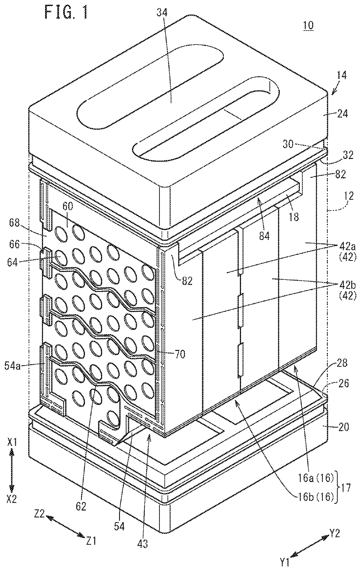
[0023]FIG. 1 is a schematic perspective view of a battery pack 10 according to this embodiment. In order to facilitate understanding, FIG. 1 shows an exterior case 12 with two-dot chain line so that the constituent components provided inside the exterior case 12 can be seen.

[0024]The battery pack 10 can be suitably applied as a portable battery pack 10 that is removably mounted in an electric vehicle (not shown) such as an electric power-assisted bicycle, electric motorcycle, etc. Accordingly, examples in which the battery pack 10 is mounted in an electric vehicle will be described below, but application thereof is not particularly limited thereto. The battery pack 10 can be applied to various devices that require electric power. Note that the top-bottom direction of the battery pack 10 will be defined as the vertical ...


PUM

PropertyMeasurementUnit
shapeaaaaaaaaaa
diameteraaaaaaaaaa
volumeaaaaaaaaaa

Abstract

A battery pack provided with a battery core pack having a plurality of battery cells held by a holding part of a cell holder, and a case for accommodating the battery core pack. The cell holder has a peripheral wall part surrounding the holding part. A plurality of slits extending along the peripheral direction on an end surface of the peripheral wall part are provided to the peripheral wall part.

Description

TECHNICAL FIELD[0001]The present invention relates to a battery pack that includes a battery core pack including a plurality of battery cells held in a cell holder.BACKGROUND ART[0002]Battery packs that have a battery core pack including a plurality of battery cells held in a cell holder, and a case accommodating the battery core pack, are known as battery packs that can be removably mounted in electric vehicles such as electric power-assisted bicycles, electric motorcycles, and the like, for example.[0003]Battery packs of this type may undergo an impact load if, for example, they fall while being attached to or removed from an electric vehicle etc. In order to avoid a situation where the impact load reaches to the battery cells through the case and cell holder and the battery cells suffer a load exceeding its load capacity, Japanese Laid-Open Patent Publication No. 2014-049225, for example, proposes providing impact mitigating ribs on the cell holder. This cell holder has a holding...

Claims


Application Information

Patent Timeline
Patent Type & Authority Applications(United States)
IPC IPC(8): H01M2/10H01M50/213
CPCH01M2/1055H01M2220/20H01M2/1077Y02E60/10H01M50/213H01M50/20H01M10/4257
Inventor MATSUMOTO, TAKASHIFUJII, NORIAKI
Owner HONDA MOTOR CO LTD
Why Eureka
Try Eureka