Data driving circuit and display device

a technology of data driving circuit and display device, which is applied in the direction of instruments, static indicating devices, etc., can solve the problems of increasing and achieve the effect of reducing the power consumption of the display panel and the power consumption of the display devi

Active Publication Date: 2022-05-05
LG DISPLAY CO LTD
View PDF0 Cites 0 Cited by
  • Summary
  • Abstract
  • Description
  • Claims
  • Application Information

AI Technical Summary

Benefits of technology

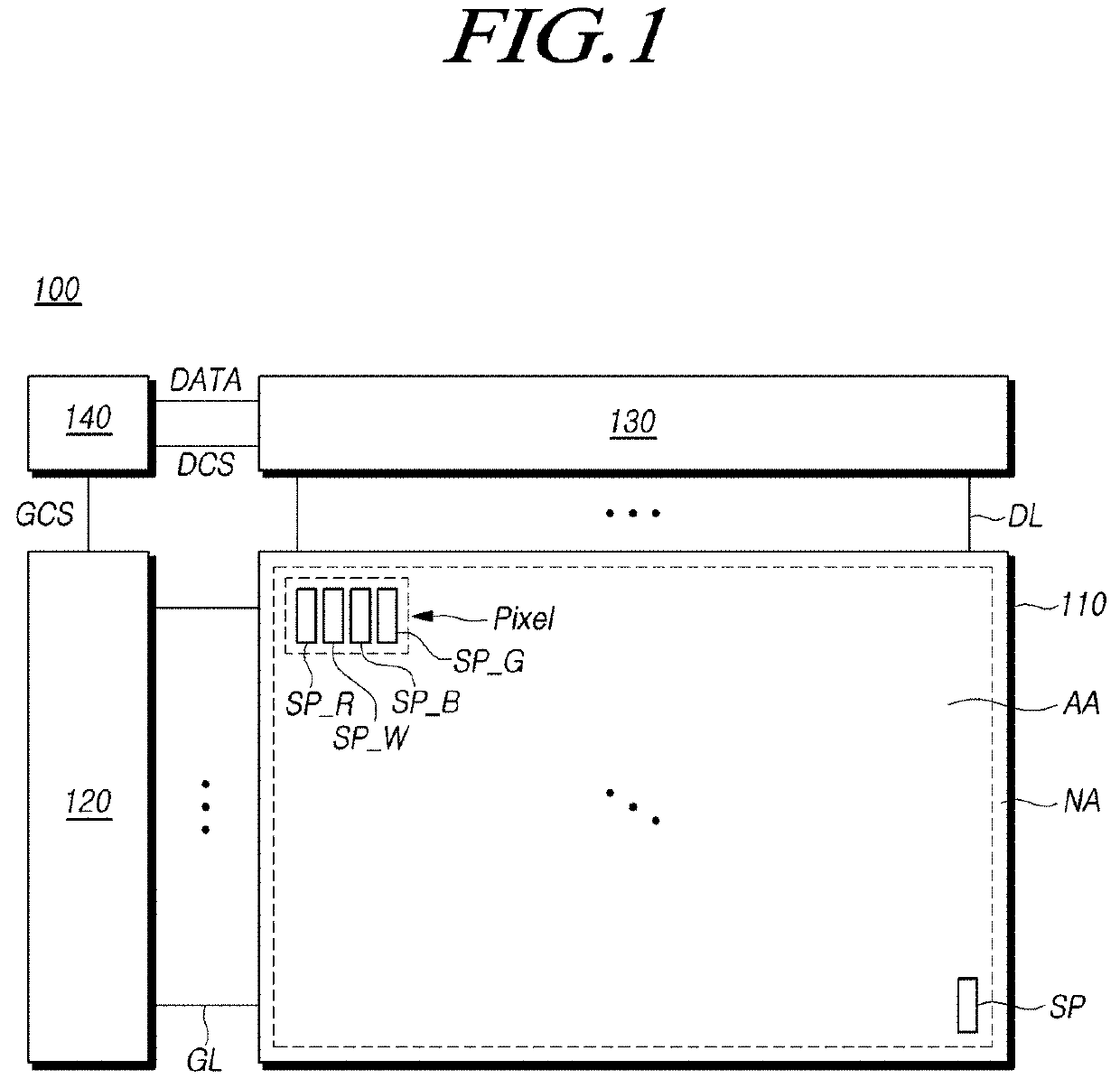
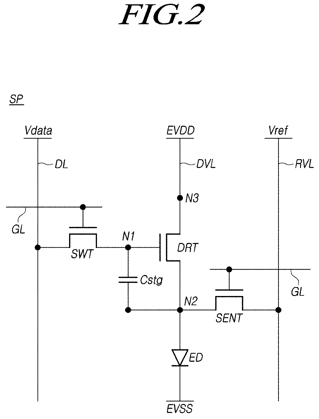
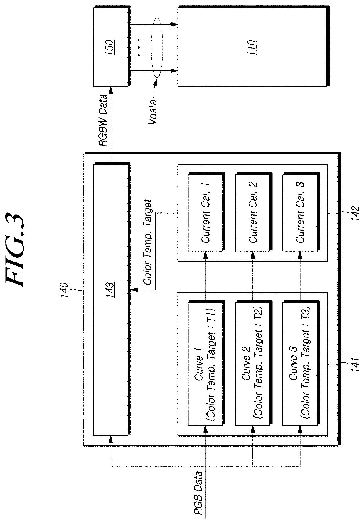
[0019]According to embodiments of the present disclosure, it is possible to display image while reducing a power consumption of a display panel by calculating a panel driving current according to a color temperature of the image displayed by the display panel and displaying the image with the color temperature at which the panel driving current is the minimum.
[0020]According to embodiments of the present disclosure, it is possible to reduce a power consumption of a display device while preventing an user from recognizing the difference in images by selecting a color temperature for minimizing a panel driving current from among the candidates of the predetermined color temperature and displaying an image according to the selected color temperature.

Problems solved by technology

In this case, as the amount of total current supplied to the display panel increases, the power consumption of the display device increases.

Method used


Image

  • Data driving circuit and display device
  • Data driving circuit and display device
  • Data driving circuit and display device

Examples


case 1

[0131 of FIG. 5 illustrates an example in which the display panel displays image A.

[0132]The controller 140 may receive image data corresponding to image A, and convert the image data into a candidate data signal based on a conversion curve according to a candidate color temperature target.

[0133]The controller 140 may calculate a panel driving current according to the converted candidate data signal, and set a final color temperature target based on the calculated panel driving current.

[0134]As an example, the candidate color temperature target may be 9,250K, 9,500K, 9,750K, 10,000K, 10,250K, or 10,500K. When displaying the image A, the calculated panel driving current according to each candidate color temperature target may be 6.85 A, 6.8 A, 6.9 A, 7 A, 7.1 A, or 7.2 A.

[0135]The controller 140 may set 9,500K, at which the panel driving current is the minimum, as the final color temperature target, and convert the image data into a data signal based on the conversion curve according...

case 2

[0139 of FIG. 6 illustrates an example in which the display panel 110 displays the image B.

[0140]When receiving red, green, and blue image data corresponding to the image B, the controller 140 may convert the received image data into a candidate data signal based on a conversion curve according to a candidate color temperature target.

[0141]The controller 140 may calculate a panel driving current according to the converted candidate data signal and set a final color temperature target.

[0142]For example, in the case of image B, if the final color temperature target is set to 9,750K, the panel driving current may be the minimum as 6.7 A.

[0143]The controller 140 may set the final color temperature target to 9,750K, and convert the red, green, and blue image data into red, green, blue and white data signals based on the conversion curve according to the set final color temperature target.

[0144]The data driving circuit 130 may output the data voltage Vdata according to the red, green, blu...


PUM


Abstract

Embodiments of the present disclosure relate to a data driving circuit and a display device. In the process of a display device converting an image data received from an outside into a data signal supplied to a data driving circuit, a final color temperature target represented by the image is variably set based on a panel driving current, so that the power consumption of a display panel displaying an image can be minimized. In addition, since the final color temperature target is varied, the luminance of the image and the user's recognition level are maintained constant, thereby improving the efficiency of the display device.

Description

CROSS REFERENCE TO RELATED APPLICATION[0001]This application claims priority from Korean Patent Application No. 10-2020-0146388, filed on Nov. 4, 2020, which is hereby incorporated by reference for all purposes as if fully set forth herein.TECHNICAL FIELD[0002]The present disclosure relates to a data driving circuit and a display device.DISCUSSION OF THE RELATED ART[0003]The growth of the information society leads to increased demand for display devices to display images and use of various types of display devices, such as liquid crystal display devices, organic light emitting display devices, etc.[0004]The display device may include a display panel in which a plurality of subpixels, signal lines and voltage lines are disposed, and various driving circuits for driving the display panel.[0005]The display device may control the luminance represented by the subpixel by controlling the amount of current supplied to the subpixel according to the type, and display an image through the dis...

Claims


Application Information

Patent Timeline
Patent Type & Authority Applications(United States)
IPC IPC(8): G09G3/3291
CPCG09G3/3291G09G2310/027G09G2320/0666G09G2300/0452G09G3/3258G09G3/32G09G2330/021G09G3/2092G09G3/3225G09G2320/0233
Inventor CHO, BYOUNGCHULLEE, JIWON
Owner LG DISPLAY CO LTD
Why Eureka
Try Eureka