Synchronous secondary emergency response system

a secondary emergency response and synchronous technology, applied in the field of emergency response, can solve the problems of increased and permanent damage, increased distress of the involved, and increased death probability, and achieve the effect of reducing the burden on the conventional emergency response system

Active Publication Date: 2022-05-05
SANGHAVI NIVEDITA LAKSHMI MEHUL
View PDF6 Cites 3 Cited by
  • Summary
  • Abstract
  • Description
  • Claims
  • Application Information

AI Technical Summary

Benefits of technology

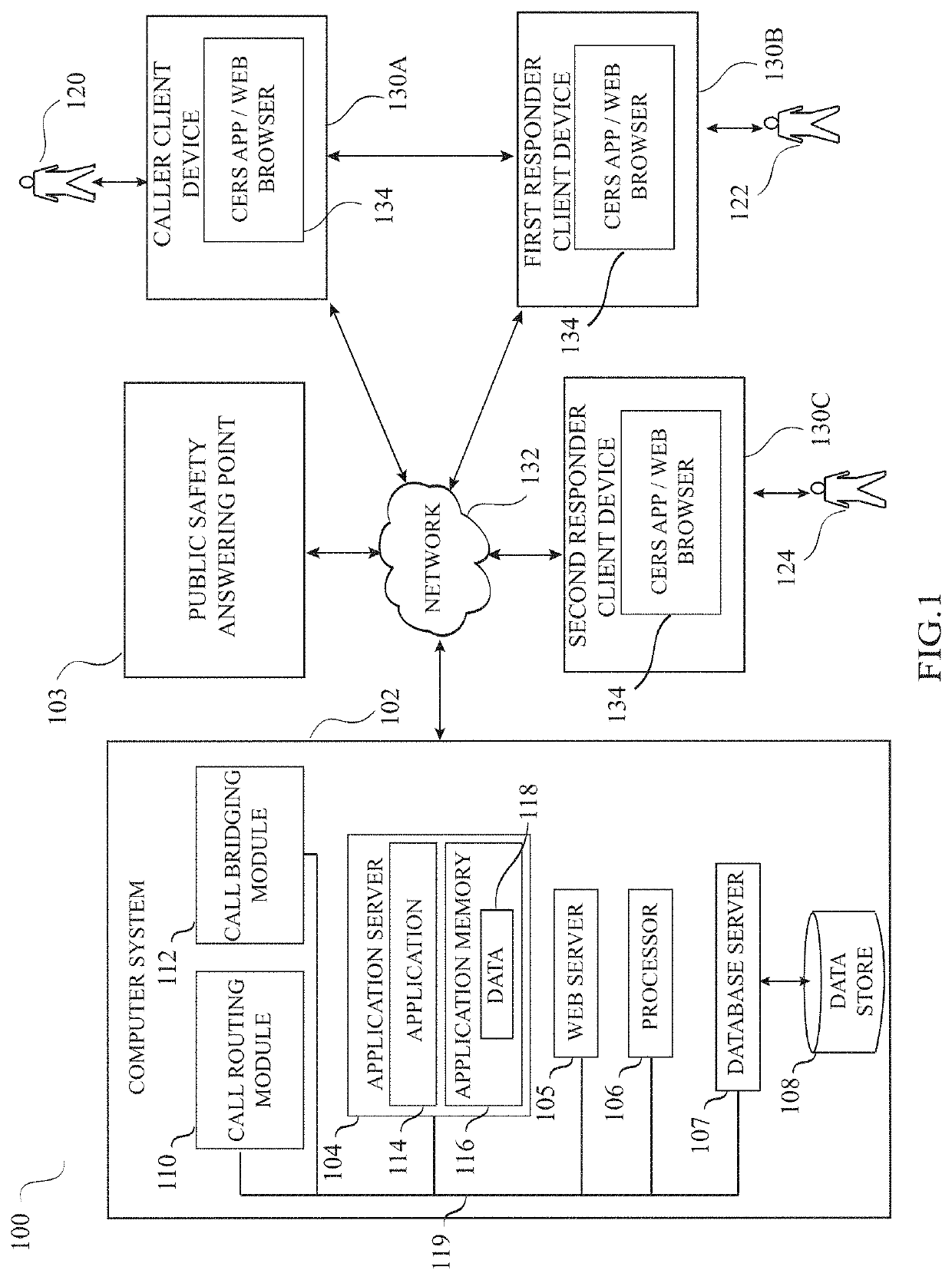
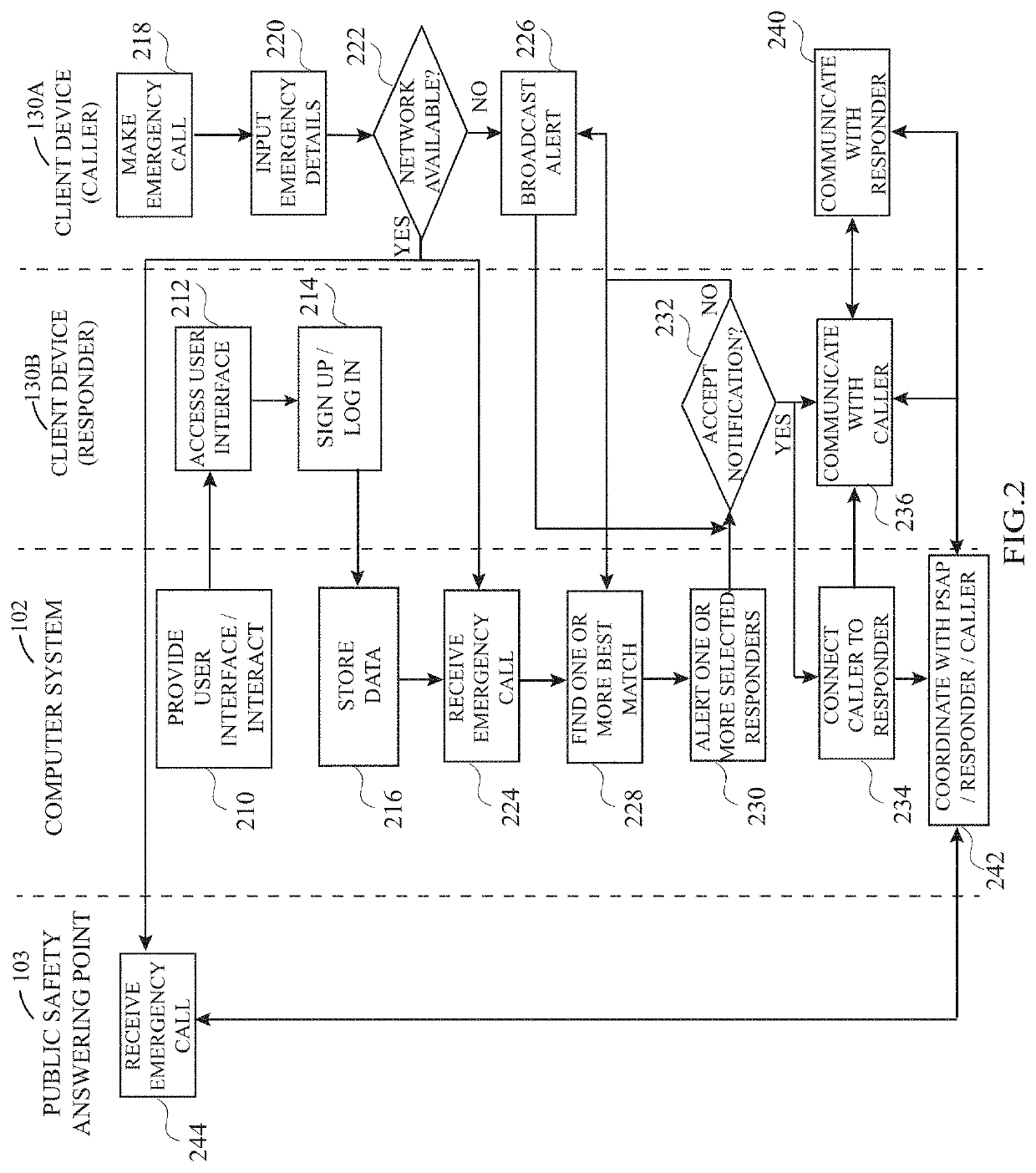
The present invention is a system and method that helps reduce the burden on conventional emergency response systems by providing a parallel communication to a central computer system. Users can dial an emergency number and receive a prompt response from a registered volunteer responder chosen based on relevant criteria. The responder can add or decline the request for help, and a communication session is maintained between the caller and responder where they can add or modify information. This system helps faster emergency response and increased participation of volunteers from the civil society.

Problems solved by technology

Response time refers to how long it takes emergency responders to arrive at the scene of an emergency after the emergency response system has been activated, A long response time can result in increased and permanent damage, a higher likelihood of fatalities, and greater distress to those involved.
For example, the optimal window for medical intervention in a cardiac arrest is often too narrow to allow for the timely arrival of trained medical professionals from EMS to the scene of a medical emergency.
In recent times the emergency systems and services have come under tremendous pressure due to reasons such as higher volume of emergency calls coupled with growth of overall population, declining funding from cash-strapped local counties and states, and higher budgets needed to modernize legacy PSAP and emergency call systems.
This mind boggling volume of calls stretches the emergency systems to the brink that ultimately pushes up the time it takes to respond to incoming requests.

Method used


Image

  • Synchronous secondary emergency response system
  • Synchronous secondary emergency response system
  • Synchronous secondary emergency response system

Examples


Embodiment Construction

[0028]In the following detailed description, numerous specific details are set forth in order to provide a thorough understanding of the invention. However, it will be understood by those skilled in the art that the present invention may be practiced without these specific details. In other instances, well-known methods, procedures and components have not been described in detail so as not to obscure the present invention.

[0029]In the interest of clarity, not all of the routine features of the implementations described herein are shown and described. It will, of course, be appreciated that in the development of any such actual implementation, numerous implementation-specific decisions must be made in order to achieve the developer's specific goals, such as compliance with application and business-related constraints including compliance with statutory and regulatory requirements, and that these specific goals will vary from one implementation to another and from one developer to ano...


PUM


Abstract

An emergency response system which can work alongside traditional public emergency response systems. The emergency response system of the present invention comprises a central computer system and client devices. In case of an emergency, when a registered user dials an emergency number, in addition to the call being received by a conventional emergency response systems, a separate parallel communication to the central computer system of the present invention gets triggered automatically. On receiving the emergency communication the computer system selects most suitable registered volunteer responders and an alert is sent to the selected registered volunteer responders. For the responders who accept the request for help, the computer system establishes a communication channel with the caller client device. This way, the emergency response system of the present invention enables participation of volunteers from the civil society in providing faster emergency response to fellow citizens.

Description

FIELD OF THE INVENTION[0001]The present invention in general is related to emergency response. More particularly, the present invention is related to a system and method for providing response to emergency situations by willing community members.BACKGROUND OF THE INVENTION[0002]Emergency response includes any systematic response to an unexpected or dangerous emergency situation. Responders to the scene of an emergency range from police and fire to emergency health personnel. Many countries provide a designated emergency number for people in emergencies to seek help from. For example, users across the United States can invoke emergency response services by dialing 911 on their phones. The 911 calls are routed by the phone service providers to the nearest ‘Public Safety Answering Point’ (PSAP), The PSAP is a service which collects the information from the distress call and in turn alerts the proper emergency responders / agencies such as the police, fire department or emergency medical ...

Claims


Application Information

Patent Timeline
Patent Type & Authority Applications(United States)
IPC IPC(8): H04W76/40H04M3/51
CPCH04W76/40H04M3/5116H04W76/50H04W4/90H04M2203/404
Inventor SANGHAVI, NIVEDITA LAKSHMI MEHUL
Owner SANGHAVI NIVEDITA LAKSHMI MEHUL
Why Eureka
Try Eureka