Street light
a technology for street lights and electronic equipment, applied in the field of street lights, can solve the problems of ineffective discharge of heat produced by electronic equipment operation, technological difficulty in making street lights, and the failure of existing street lights to provide an effective heat dissipation mechanism for electronic equipment, so as to prevent any liquid from flowing and dissipate heat from electronic equipmen
- Summary
- Abstract
- Description
- Claims
- Application Information
AI Technical Summary
Benefits of technology
Problems solved by technology
Method used
Image
Examples
first embodiment
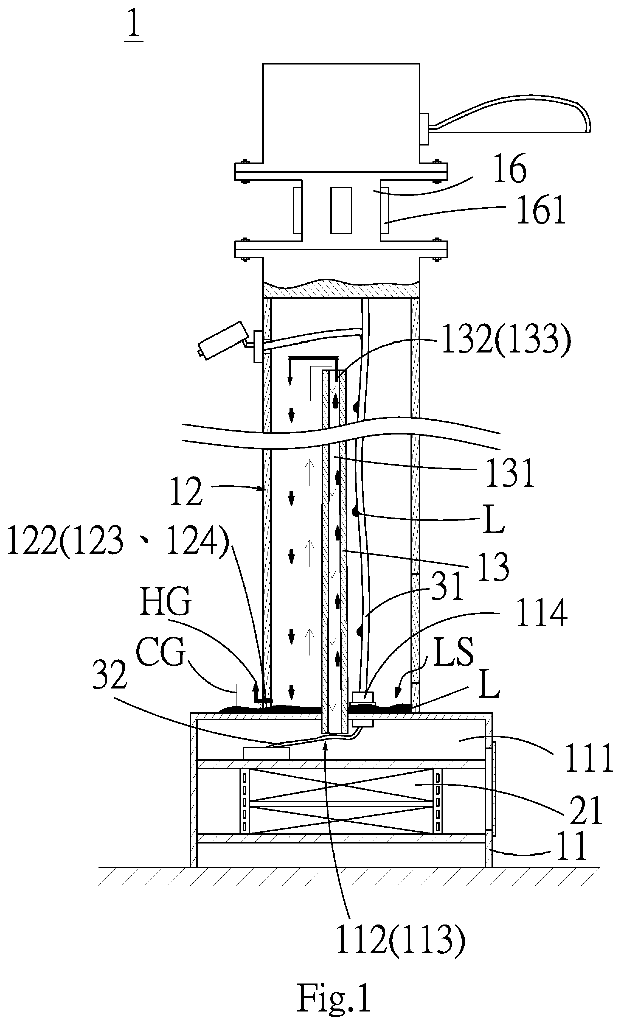
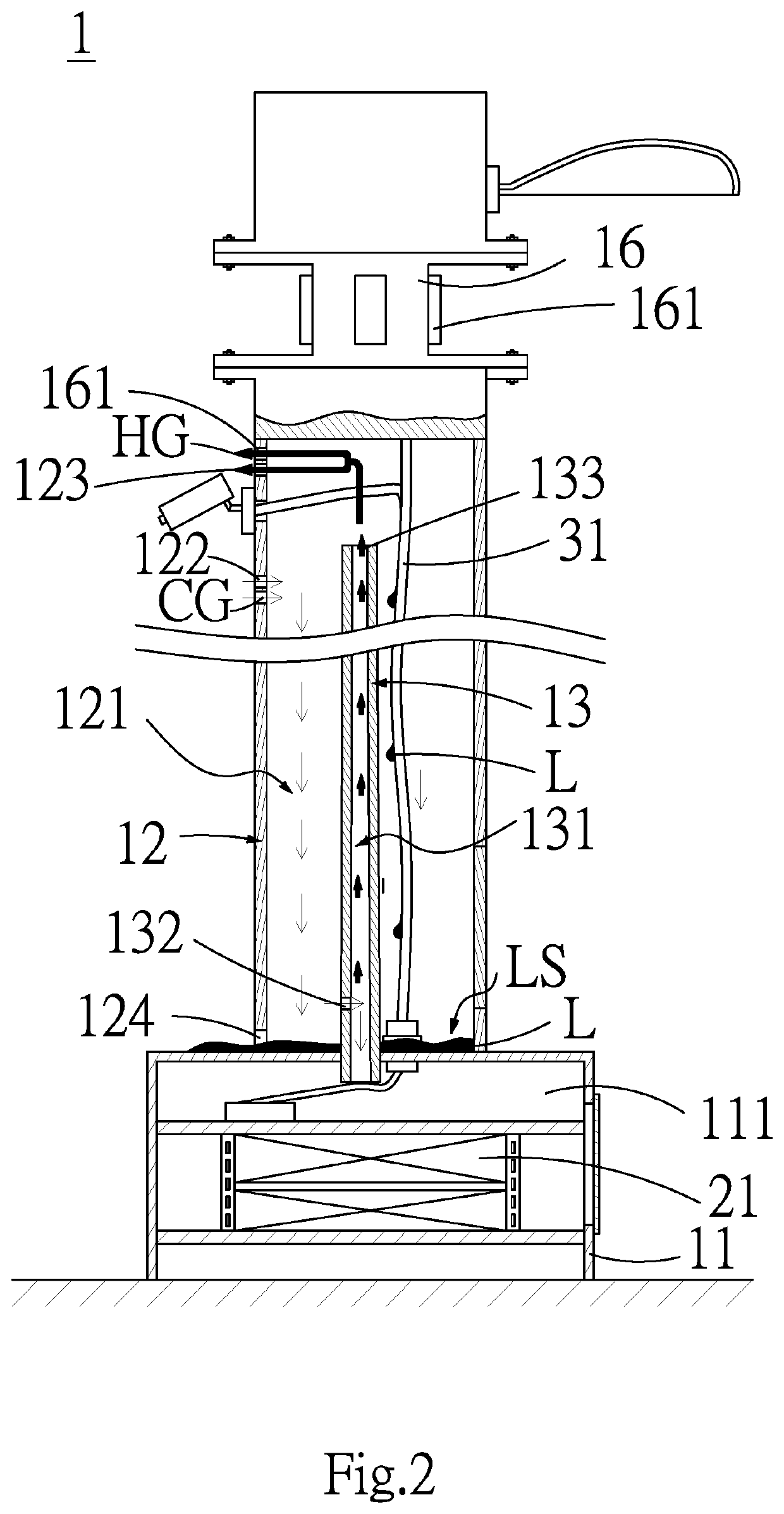
[0036]Referring to FIGS. 1 to 2, a street light 1 according to the first embodiment includes a light base 11, a pole 12 and a chimney structure 13.
[0037]The light base 11 includes a base internal space 111, a base inlet 112 and a base outlet 113. The base internal space 111 is used to accommodate a base electronic device 21 and allow it to operate therein. The pole 12 includes a pole internal space 121, a pole inlet 122, a pole outlet 123 and a pole drain 124. The chimney structure 13 includes a chimney internal space 131, a chimney inlet 132 and a chimney outlet 133.
[0038]In this embodiment, the pole inlet 122 is used to provide gas intake for the pole internal space 121 and allow a cold gas(such as cold air) CG to be introduced to the pole internal space 121. The chimney inlet 132 is used to provide gas intake for the chimney internal space 131 and allow a part of the cold gas CG in the pole internal space 121 to be introduced to the chimney internal space 131. The base inlet 112 ...
second embodiment
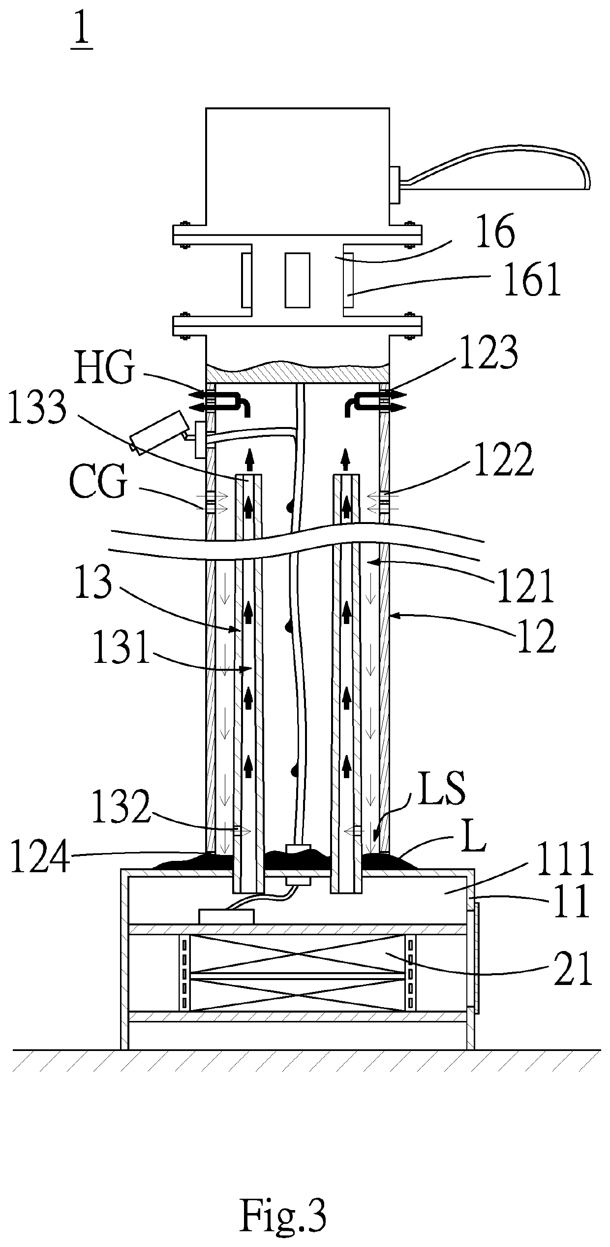
[0049]As shown in FIGS. 3 to 5, the second embodiment is very similar to the above first embodiment, with a primary difference in that, the street light 1 in this embodiment is provided with a plurality of chimney structures 13 for more effectively allowing a part of the cold gas CG to be introduced to the base internal space 111 and a part of the hot gas HG to be exhausted from the base internal space 111 so as to accomplish heat dissipation for the base electronic device 21.
[0050]In this embodiment, as shown in FIG. 4, it should be noted that the street light 1 can selectively be provided with a carrier 17 for carrying a pole electronic device 22 that can thus operate inside the street light 1. The carrier 17 is placed at a predetermined position in the pole internal space 121 by means of the chimney structure 13.
[0051]In this embodiment, the antenna base 16 can selectively be formed with a cover 162 for covering the antenna 161. The cover 162 can be made of PTFE (polytetrafluoroe...
third embodiment
[0053]As shown in FIGS. 6 to 7, the third embodiment is very similar to the above embodiments, with a primary difference in that, the chimney structure 13 in this embodiment includes an inlet chimney sub-structure 134 and an outlet chimney sub-structure 135, and the liquid space LS is surrounded by the light base 11, the pole 12, the inlet chimney sub-structure 134 and the outlet chimney sub-structure 135. The inlet chimney substructure 134 and the outlet chimney sub-structure 135 are both provided in the pole internal space 121, wherein the inlet chimney sub-structure 134 includes an inlet chimney sub-structure internal space 1341, and the outlet chimney sub-structure 135 includes an outlet chimney sub-structure internal space 1351. In this embodiment, the chimney inlet 132 is situated at the inlet chimney sub-structure 134, and the chimney outlet 133 is situated at the outlet chimney sub-structure 135.
[0054]The chimney inlet 132 is used to introduce a part of the cold gas CG in th...
PUM
 Abstract
Description
Claims
Application Information
 - R&D
- Intellectual Property
- Life Sciences
- Materials
- Tech Scout
- Unparalleled Data Quality
- Higher Quality Content
- 60% Fewer Hallucinations
Browse by: Latest US Patents, China's latest patents, Technical Efficacy Thesaurus, Application Domain, Technology Topic, Popular Technical Reports.
© 2025 PatSnap. All rights reserved.Legal|Privacy policy|Modern Slavery Act Transparency Statement|Sitemap|About US| Contact US: help@patsnap.com


