A Sterilisation Device for Sterilising a Section of a Catheter Tube and a Method for Sterilising a Section of a Catheter Tube

a technology of sterilisation device and catheter tube, which is applied in the direction of catheter, radiation, disinfection, etc., can solve the problems of reducing the sterilisation capability of the device, reducing the risk of infection of the patient, and ultraviolet light at germicidal intensity being potentially carcinogenic to the patien

Pending Publication Date: 2022-05-19
VIOBAC APS
View PDF0 Cites 2 Cited by
  • Summary
  • Abstract
  • Description
  • Claims
  • Application Information

AI Technical Summary

Problems solved by technology

In some cases, this catheter tube is kept in place in the patient for a prolonged period of time, which may allow germs to move along the inside and/or outside of the ex vivo tubing section to reach the in vivo tubing section and thus enter into the body of the patient, thereby risking an infection of the patient.
A drawback is that ultraviolet light at germicidal intensity is potentially carcinogenic to the patient.
A light shield surrounding the ultraviolet ligh

Method used


Image

  • A Sterilisation Device for Sterilising a Section of a Catheter Tube and a Method for Sterilising a Section of a Catheter Tube
  • A Sterilisation Device for Sterilising a Section of a Catheter Tube and a Method for Sterilising a Section of a Catheter Tube
  • A Sterilisation Device for Sterilising a Section of a Catheter Tube and a Method for Sterilising a Section of a Catheter Tube

Examples


Embodiment Construction

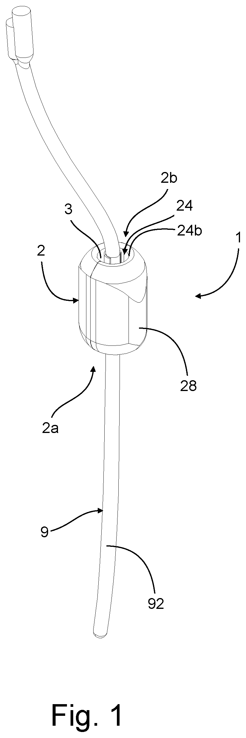
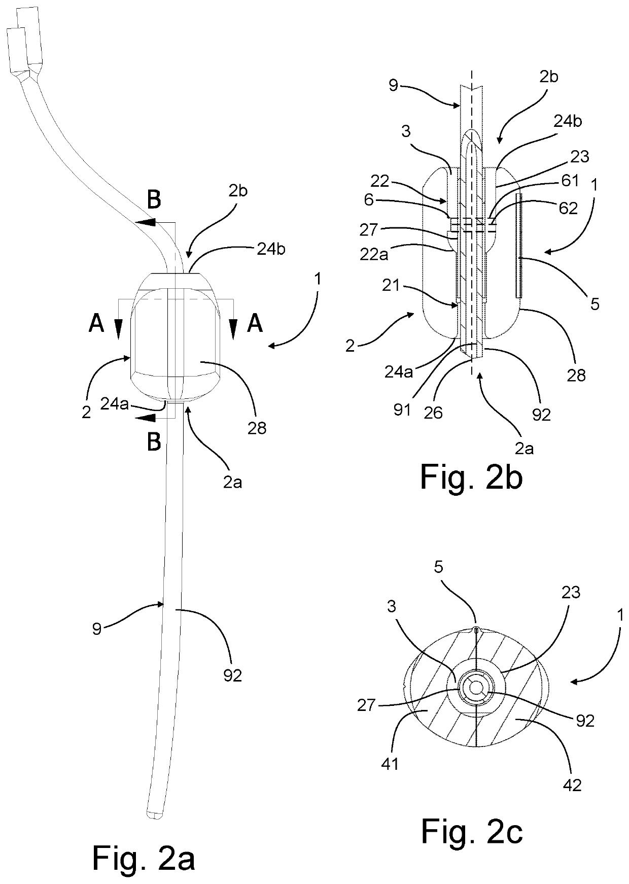
[0079]Referring first to FIGS. 1 and 2a, a sterilisation device 1 is shown with a catheter tube 9 extending there through. The sterilisation device 1 comprises a casing 2 with a proximal end 2a, a distal end 2b, and an outer surface 28. The proximal end 2a of the casing 2 is intended to be oriented towards a patient and the distal end 2b of the casing 2 is intended to be oriented away from the patient. The outer surface 28 of the casing 2 is facing the exterior of the sterilisation device 1 and has a streamlined, curved shape from the proximal end 2a to the distal end 2b without sharp edges or corners in order to prevent causing a pressure ulcer if the sterilisation device 1 should end up beneath the patient. The maximum axial length of the sterilisation device 1 from the proximal end 2a to the distal end 2b is about 1.5 times the maximum outer diameter of the sterilisation device 1.

[0080]The casing 2 comprises a through hole 24 with a circular proximal opening 24a located at the pr...


PUM


Abstract

A sterilisation device for sterilising a section of a catheter tube includes a casing including a proximal end, a distal end, an attachment portion, a sterilisation chamber, and a through hole extending through the attachment portion and the sterilisation chamber, the through hole having a distal opening positioned at the distal end of the casing and leading into the sterilisation chamber, the attachment portion being configured to retain a section of a catheter tube in the through hole; and at least one light source configured to emit germicidal light into the sterilisation chamber of the casing. A diameter of the distal opening of the through hole is greater than a diameter of the through hole at the attachment portion, so that when the catheter tube is retained in the through hole, an air gap is formed between the sterilisation chamber at the distal opening and the catheter tube.

Description

CROSS-REFERENCE TO RELATED APPLICATIONS[0001]This application is the U.S. national phase of, and claims priority to, International Application No. PCT / DK2020 / 050089, filed Apr. 3, 2020, which designated the U.S. and which claims priority to Danish Patent Application No. PA201970218 filed Apr. 5, 2019.FIELD OF THE INVENTION[0002]The invention relates to a sterilisation device for a catheter tube and to a method for sterilising a section of a catheter tube.BACKGROUND[0003]During various medical procedures, an artificial access way into the body of a patient is sometimes required, for instance to supply or remove fluids, administer pharmaceuticals, or to perform a wide variety of tasks. For this purpose, a catheter tube may be inserted through an opening of the body of the patient with an in vivo tubing section of the catheter tube positioned in vivo, i.e. inside the body of the patient, and an ex vivo tubing section positioned ex vivo, i.e. outside the body of the patient. In some cas...

Claims


Application Information

Patent Timeline
IPC IPC(8): A61L2/10
CPCA61L2/10A61L2202/11A61L2202/24A61L2202/123A61L2202/122A61L2/08A61L2202/16A61M25/0017A61M2025/0019
Inventor KOPPEN, KASPERANDERSEN, MADS ORBÆKHALILI, ANDRIM
Owner VIOBAC APS
Why Eureka
Try Eureka