Accessible charging device

a charging device and charging port technology, applied in the direction of charging stations, transportation and packaging, instruments, etc., can solve the problems of poorer perceptibility and increased costs for the unused screen area

Pending Publication Date: 2022-05-19
SIEMENS AG
View PDF3 Cites 0 Cited by
  • Summary
  • Abstract
  • Description
  • Claims
  • Application Information

AI Technical Summary

Benefits of technology

[0006]The charging device according to the invention can therefore be comfortably controlled by a user by touching the touch-sensitive screen, wherein the control unit outputs a graphical user interface in response to these interactions of the user. The graphical user interface can display, for example, variable graphical and textual content in order to guide the user through the actual charging procedure or an authentication and a payment procedure, insofar as these steps are provided by the operator of the charging device. The graphical user interface can be provided with operating elements which can be actuated by touch at the location of the operating elements on the screen and the like, as is generally known in the field of graphical interfaces for devices with touch-sensitive screens. However, the charging device according to the invention is distinguished in that, in contrast to the prior art, the graphical user interface is displayed on only a partial area of the touch-sensitive screen. The screen area not used for the graphical user interface can, for example, remain blank or can be filled with a color, a color gradient, a static or animated background image or static or animated graphical pattern, wherein static content is preferred due to the lower risk of distraction of the user. As a result, in contrast to the widespread technical teaching of using the available screen area as completely as possible for a graphical user interface, the area of the screen to be perceived by a user and to be operated by touch is reduced to the (in particular rectangular) partial area, which is normally associated with a poorer perceptibility and increased costs for the unused screen area. The invention overcomes these preconceptions and exploits the reduction of the screen area used for the graphical user interface to the partial area of the screen for an increase in ease of use. In order to do this, the control unit of the charging device is configured to variably choose a vertical distance between the partial area and a lower edge of the screen. This means that, in the operation of the charging device, the partial area and the graphical user interface displayed therein can be disposed at different heights on the screen and therefore at different heights above the base around the charging device without the screen itself having to be movably or adjustably suspended. As a result, the charging device is configured to be easily usable by people of different heights or, for example, by wheelchair users as well, since the graphical user interface can be displayed for a relatively short or wheelchair-using user with no or a small vertical distance from the lower edge of the screen and for a relatively tall user with a larger vertical distance from the lower edge of the screen.
[0012]However, the charging device can also be equipped with a sensor unit which is connected to the control unit and is configured to detect the user. The control unit is configured to adjust the vertical distance depending on a sensor signal of the sensor unit. The sensor unit can include, for example, a camera, an array of infrared sensors or the like with which the position of the eyes or the head of the user can be detected when approaching the charging device. As a result, the charging device can decide whether a relatively smaller or greater vertical distance for the positioning of the partial area will be comfortable for the user. Nevertheless, following the positioning performed automatically on the basis of the sensor signal, the partial area can additionally be positionable by the user, as described above.

Problems solved by technology

As a result, in contrast to the widespread technical teaching of using the available screen area as completely as possible for a graphical user interface, the area of the screen to be perceived by a user and to be operated by touch is reduced to the (in particular rectangular) partial area, which is normally associated with a poorer perceptibility and increased costs for the unused screen area.

Method used


Image

  • Accessible charging device
  • Accessible charging device
  • Accessible charging device

Examples


Embodiment Construction

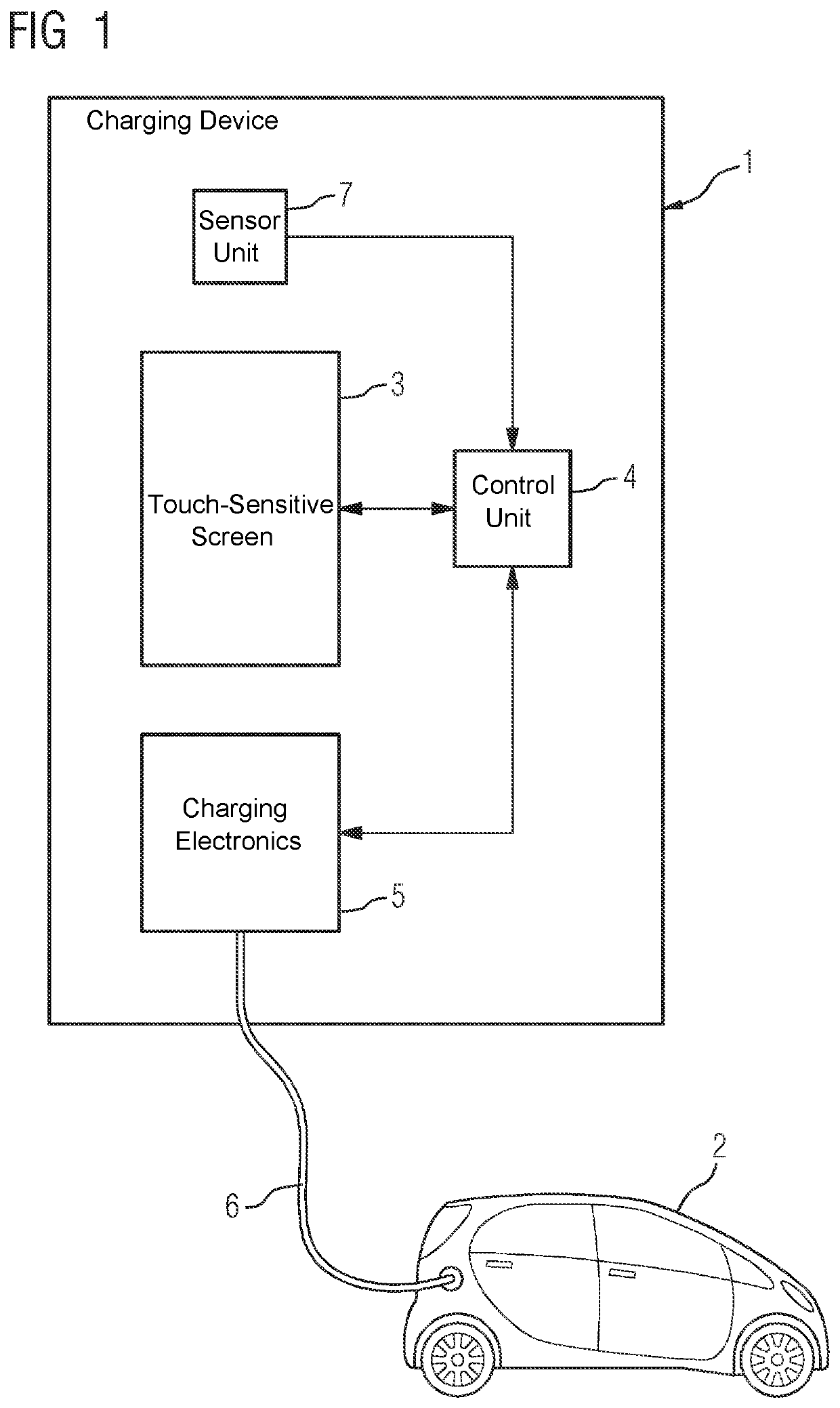
[0023]Referring now to the figures of the drawings in detail and first, particularly, to FIG. 1 thereof, there is seen a first embodiment example of a charging device 1 according to the invention which is shown in a block diagram. The charging device 1 has a touch-sensitive screen 3 which is disposed in this case in a portrait orientation on the charging device 1. The touch-sensitive screen 3 serves primarily to request a charging procedure for an electric vehicle 2 and, if necessary, to predefine some of its boundary conditions, such as a desired energy quantity, a charging power or charging speed or a cost limit. The charging device 1 can be controlled by a user by touching the touch-sensitive screen 3 and a graphical user interface displayed on the screen 3.

[0024]The touch-sensitive screen 3 is connected to a control unit 4 and transmits information to it relating to interactions of a user with the screen 3. The screen 3 further receives the screen content to be displayed on the ...


PUM


Abstract

A charging device for an electric vehicle includes a touch-sensitive screen and a control unit connected to the screen. The control unit is configured to detect an interaction of a user on the basis of a touch of the screen and to output a graphical user interface on the screen according to the detected interaction. The control unit is further configured to display the user interface on only a partial area of the screen and to variably choose a vertical distance between the partial area and a lower edge of the screen.

Description

CROSS-REFERENCE TO RELATED APPLICATION[0001]This application claims the priority, under 35 U.S.C. § 119, of German Patent Application DE 10 2020 214 318.8, filed Nov. 13, 2020; the prior application is herewith incorporated by reference in its entirety.FIELD AND BACKGROUND OF THE INVENTION[0002]The invention relates to a charging device for an electric vehicle.[0003]Charging devices for electric vehicles are becoming increasingly widespread with the ongoing decarbonization of road traffic. Charging devices are intended not only to perform their fundamental technical task, but also to be simply and conveniently usable.SUMMARY OF THE INVENTION[0004]It is accordingly an object of the invention to provide an improved accessible charging device, which overcomes the hereinafore-mentioned disadvantages of the heretofore-known devices of this general type and which is simply and conveniently usable.[0005]With the foregoing and other objects in view there is provided, in accordance with the ...

Claims


Application Information

Patent Timeline
Patent Type & Authority Applications(United States)
IPC IPC(8): G06F3/0488G06F3/0484B60L53/30
CPCG06F3/04886B60L53/305G06F3/04847Y02T10/70Y02T10/7072Y02T90/12Y02T90/16B60L2250/16
Inventor WOHLGEMUTH, PIERRESTOLZE, STEFFENSONNTAG, JOERGKARMAZIN, MARKUS
Owner SIEMENS AG
Why Eureka
Try Eureka