Complex decommissioning method for nuclear facility

a nuclear facility and complex technology, applied in the field of complex decommissioning methods of nuclear facilities, can solve the problems of excessive working time for cutting and decommissioning of nuclear reactor pressure vessels, and achieve the effect of stably cutting and reducing working tim

Pending Publication Date: 2022-05-26
KOREA HYDRO & NUCLEAR POWER CO LTD
View PDF18 Cites 0 Cited by
  • Summary
  • Abstract
  • Description
  • Claims
  • Application Information

AI Technical Summary

Benefits of technology

[0013]According to the embodiment of the present invention, a nuclear reactor pressure vessel is cut and decommissioned by a cutter capable of elevating and moving in a circumferential direction inside a cavity while being fixed by a fixture inside the cavity of bio-protective concrete, thereby stably cutting and decommissioning the nuclear reactor pressure vessel while reducing a working time.

Problems solved by technology

However, there is a problem in that it requires an excessive working time for cutting and decommissioning the nuclear reactor pressure vessel.

Method used


Image

  • Complex decommissioning method for nuclear facility
  • Complex decommissioning method for nuclear facility
  • Complex decommissioning method for nuclear facility

Examples


Embodiment Construction

[0020]The present invention will be described more fully hereinafter with reference to the accompanying drawings, in which embodiments of the invention are shown. As those skilled in the art would realize, the described embodiments may be modified in various different ways, all without departing from the spirit or scope of the present invention. The drawings and description are to be regarded as illustrative in nature and not restrictive. Like reference numerals designate like elements throughout the specification.

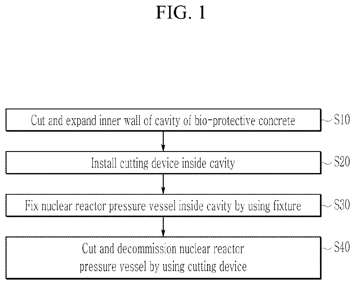
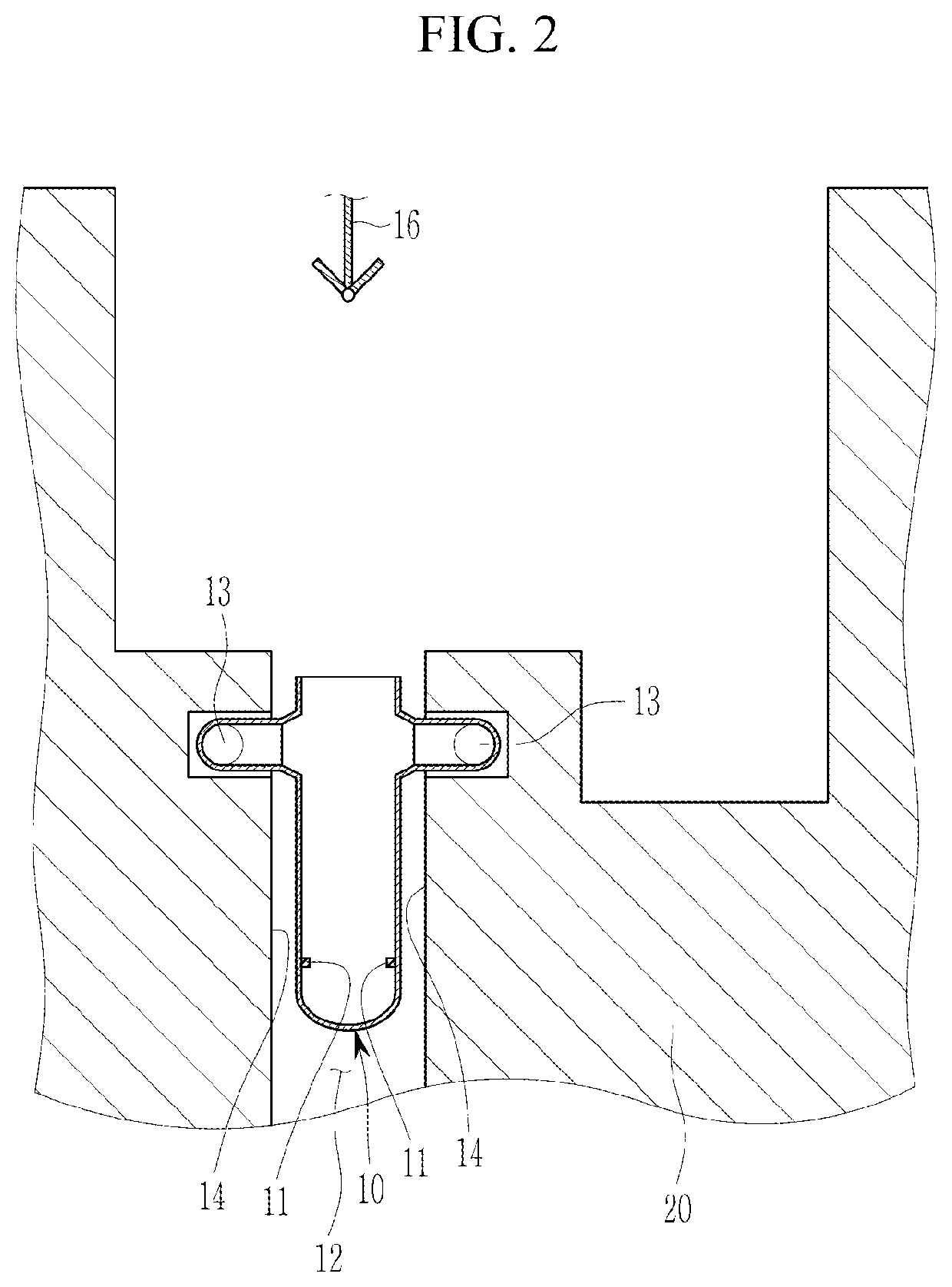
[0021]FIG. 1 schematically illustrates a flowchart of a method for decommissioning a nuclear facility according to an embodiment of the present invention, and FIG. 2 schematically illustrates a part of a nuclear facility according to an embodiment of the present invention.

[0022]As illustrated in FIG. 1 and FIG. 2, a nuclear facility may include a nuclear reactor pressure vessel 10, a plurality of pipes 13 directly connected to the nuclear reactor pressure vessel 10, bio-pr...


PUM

PropertyMeasurementUnit
pressureaaaaaaaaaa
driving forceaaaaaaaaaa
lengthaaaaaaaaaa

Abstract

A method for complex-decommissioning a nuclear facility is disclosed. The method for complex-decommissioning the nuclear facility includes: cutting and expanding an inner wall of the cavity; installing a cutting device that cuts and decommissions the nuclear reactor pressure vessel inside the cavity; fixing the nuclear reactor pressure vessel inside the cavity by using a fixture; and cutting and decommissioning the nuclear reactor pressure vessel fixed inside the cavity by using a cutting device.

Description

TECHNICAL FIELD[0001]The present invention relates to a method for decommissioning a nuclear facility.BACKGROUND ART[0002]Generally, among nuclear facilities used for nuclear power generation, a pressurized water reactor type of nuclear power plant includes a nuclear reactor pressure vessel and bio-protective concrete surrounding the nuclear reactor pressure vessel.[0003]When decommissioning a nuclear facility, it is necessary to separate the nuclear reactor pressure vessel from the bio-protective concrete, and to cut and decommission the nuclear reactor pressure vessel.[0004]However, there is a problem in that it requires an excessive working time for cutting and decommissioning the nuclear reactor pressure vessel.DISCLOSURETechnical Problem[0005]An embodiment of the present invention is to provide a complex decommissioning method of a nuclear facility that may stably cut and decommission a nuclear reactor pressure vessel while reducing a working time.Technical Solution[0006]An emb...

Claims


Application Information

Patent Timeline
Patent Type & Authority Applications(United States)
IPC IPC(8): G21D1/00B23D1/18B23D33/04
CPCG21D1/003B23D33/04B23D1/18B28D1/088B28D1/045B23D57/0084G21F9/28
Inventor HWANG, YOUNG HWANHWANG, SEOK-JUYOON, JU-YOUNGKIM, CHEON-WOO
Owner KOREA HYDRO & NUCLEAR POWER CO LTD
Why Eureka
Try Eureka