
Monitoring system

a monitoring system and monitoring device technology, applied in the direction of electric programme control, program control, instruments, etc., can solve the problems of not allowing energization of the analysis device, affecting and taking time to restart the operation, so as to prevent the operation of the analysis system

Pending Publication Date: 2022-06-02
SHIMADZU CORP
View PDF11 Cites 0 Cited by
  • Summary
  • Abstract
  • Description
  • Claims
  • Application Information

AI Technical Summary

Benefits of technology

The present invention aims to prevent the analysis system from stopping its operation when an error occurs in the analysis device of the monitoring system.

Problems solved by technology

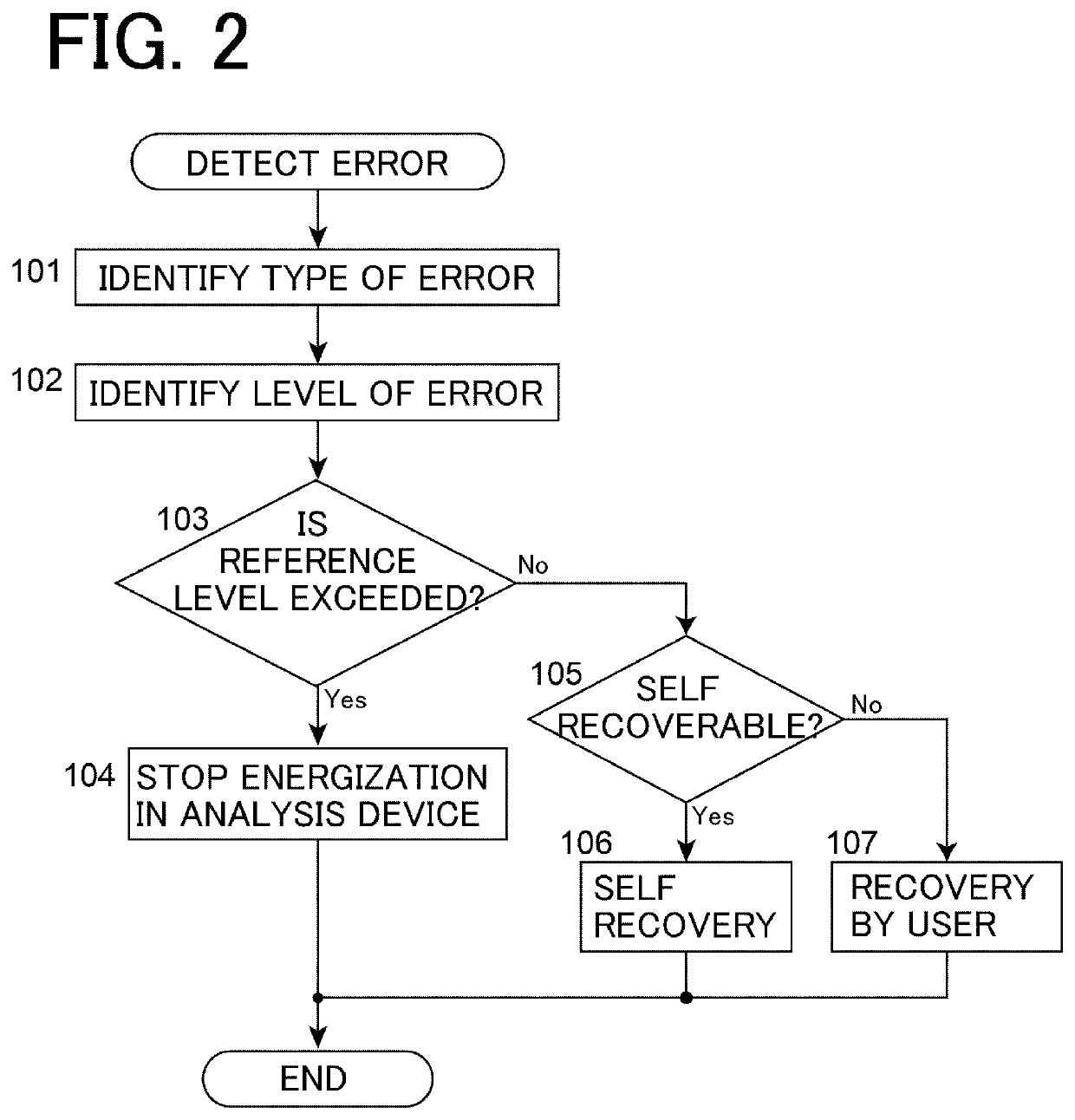
In a case where the management device detects occurrence of an error in the analysis device by a signal output from the analysis system, the management device cuts off power supply to each constituent of the analysis device to stop energization in the analysis device, and does not allow energization of the analysis device until the error is resolved.
However, in the above measure, even in a case where the error that occurs in the analysis device is a minor error that can be autonomously recovered in the analysis device (error that can be recovered without turning off the power supply), all the energization in the power supply device is stopped, and it takes time to restart the operation.

Method used


Image

  • Monitoring system
  • Monitoring system

Examples


Embodiment Construction

[0012]Hereinafter, an embodiment of a monitoring system according to the present invention will be described with reference to the drawings.

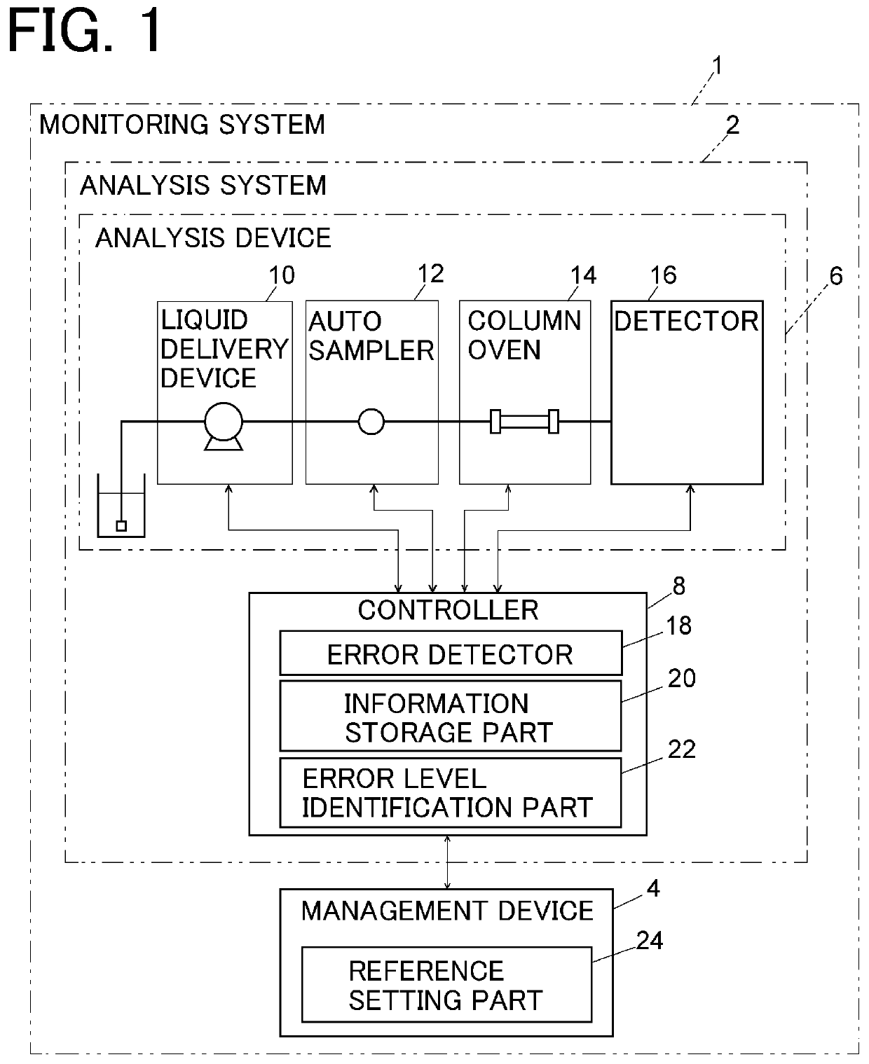
[0013]As illustrated in FIG. 1, the monitoring system 1 includes an analysis system 2 and a management device 4. The analysis system 2 includes an analysis device 6 and a controller 8.

[0014]The analysis device 6 is a liquid chromatograph including a liquid delivery device 10, an autosampler 12, a column oven 14, and a detector 16. The analysis device 6 injects a sample by the autosampler 12 into a mobile phase sent by the liquid delivery device 10, separates components in the sample by a separation column arranged in the column oven 14, and detects the separated components by the detector 16. The controller 8 is provided to be able to communicate with each of the liquid delivery device 10, the autosampler 12, the column oven 14, and the detector 16 of the analysis device 6, and controls the operation of the analysis device 6. The controller 8 is...


PUM


Abstract

To prevent operation of an analysis system from being stopped every time an error occurs in an analysis device of a monitoring system. A monitoring system includes an analysis device provided with a plurality of sensors, an error detector configured to detect occurrence of an error in the analysis device based on an output signal of a plurality of the sensors, and to identify a type of the detected error, an information storage part storing levels set in advance for each of a plurality of types of errors that may occur in the analysis device, and an error level identification part configured to identify a level of an error detected by the error detector based on information stored in the information storage part Where an error occurs in the analysis device, a measure according to the level of the error identified is executed in the analysis device.

Description

BACKGROUND OF THE INVENTION1. Field of the Invention[0001]The present invention relates to a monitoring system.2. Description of the Related Art[0002]As introduction into product and quality processes progresses, it is important to continuously monitor the manufacturing process as automatically as possible and confirm that the required product quality is ensured. As a method for the above, the employment of Process Analytical Technology (PAT) has been promoted, and introduction of the above is in progress particularly in the oil and chemical industry.[0003]The introduction of PAT has been actively studied in the pharmaceutical industry in recent years. The introduction of the PAT not only improves the reliability and robustness of the manufacturing process but also has a cost reduction effect. A liquid chromatograph (LC) is also an element necessary for a PAT system, and technological development for real popularization is in progress.[0004]One of targets of monitoring by PAT is a m...

Claims


Application Information

Patent Timeline
Patent Type & Authority Applications(United States)
IPC IPC(8): G05B19/418
CPCG05B19/41875G05B2219/32368G01D21/02G05B2219/32287
Inventor NAGAI, YUSUKE
Owner SHIMADZU CORP
Learn More