
Joining tool for joining a deformable element to a workpiece

a technology of joining tool and deformable element, which is applied in the direction of metal-working hand tools, fastener tools, manufacturing tools, etc., can solve the problems of not being easily adaptable the tool is not easily adjustable to the type of insert, etc., to achieve the effect of convenient us

Active Publication Date: 2022-06-09
DUBUIS & CIE
View PDF14 Cites 0 Cited by
  • Summary
  • Abstract
  • Description
  • Claims
  • Application Information

AI Technical Summary

Benefits of technology

The present invention provides a joining tool for joining deformable elements to a workpiece. The tool has several technical advantages. Firstly, it can be easily used with deformable elements of different sizes and geometries. Secondly, it has a removable nose piece that can be easily adapted to different sizes of inserts or deformable elements. The nose is movable through the hydraulic system and allows for better repositioning of the setting forces. Thirdly, the tool has a threaded dowel and a contact sensor to detect the displacement of the dowel. This activates the electrical motor to screw the deformable element into the dowel. The sliding unit around the electrical motor is slidable with regard to the electrical motor and allows for better repositioning of the setting forces. Overall, the invention provides a versatile and efficient tool for joining deformable elements to workpieces.

Problems solved by technology

The tool is proving satisfactory but is designed to be used with nuts and is not easily adaptable to deformable elements with a threaded shaft.
Besides, the tool is not easily adjustable to the type of insert to be set and is notably not adjustable to deformable elements having different geometries or diameters.
Such riveting apparatus are well known, but not adapted to be used with deformable elements as above-mentioned and not adaptable to different size of deformable elements.

Method used


Image

  • Joining tool for joining a deformable element to a workpiece
  • Joining tool for joining a deformable element to a workpiece
  • Joining tool for joining a deformable element to a workpiece

Examples


Embodiment Construction

[0029]On the different figures, the same reference signs designate identical or similar elements.

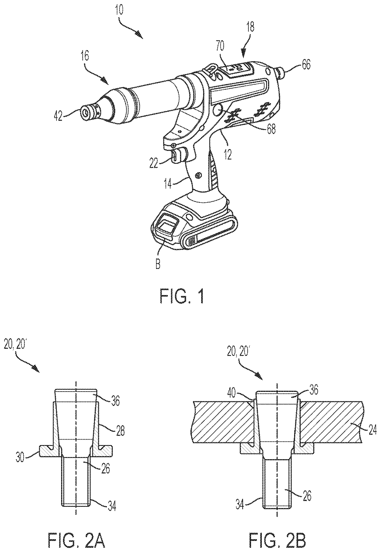
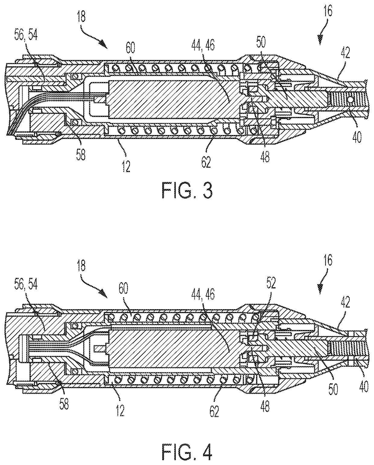
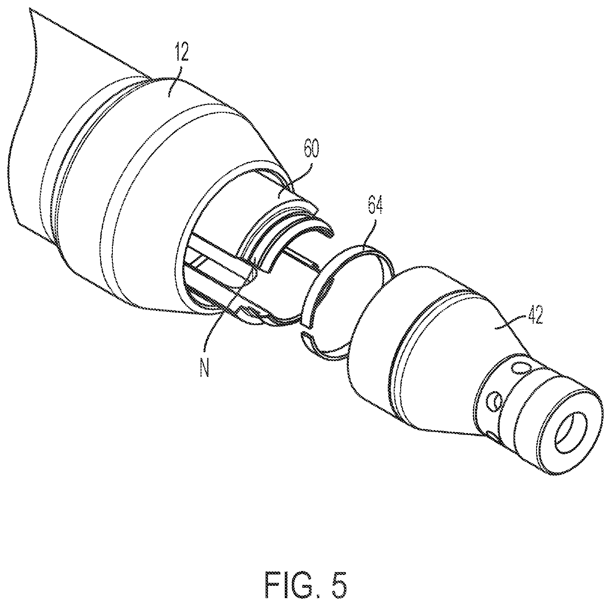
[0030]The joining tool 10, as illustrated in FIG. 1, comprises a housing 12 with a handle 14. The housing 12 receives a rechargeable electrical battery B detacheably connected to the foot of the handle 14. The battery may be a 18V Li-ion battery or any similar battery. The tool 10 further comprises a fastening unit 16 adapted to receive a deformable element 20 and a transmission unit 18 arranged between the fastening unit 16 and the handle 14. The joining tool 10 further comprises a trigger system that includes a trigger 22 mounted on the housing 12 that allows a user to initiate a setting action for securing the deformable element 20 to a workpiece 24. The trigger 22 is for instance arranged on the handle 14. As depicted on FIG. 1, the fastening unit 16 and transmission unit 18 longitudinally extend in a direction sensibly orthogonal to the handle.

[0031]The deformable element (or blind ...


PUM

PropertyMeasurementUnit
Pressureaaaaaaaaaa
Compressibilityaaaaaaaaaa

Abstract

A power tool for joining a deformable element having a threaded shaft to a workpiece. The joining tool comprising a threaded dowel adapted to receive the threaded shaft and rotatably within the housing. A nose is arranged around the threaded dowel, and the dowel is slidably movable relative to the nose. A motor drives a drive train to rotate the threaded dowel. A hydraulic system drives another drive train to move the threaded shaft and compress the deformable element. The joining tool includes a sliding unit. The nose is attachable to the sliding unit, and in an attached position the nose is slidably connected to the housing so that the hydraulic system may move the nose axially to compress the deformable element.

Description

CROSS-REFERENCE TO RELATED APPLICATION[0001]This application claims priority from European Patent Application No. 20315485.1, filed on Dec. 7, 2020, the disclosure of which is incorporated herein by reference.BACKGROUND OF THE INVENTION[0002]The present invention relates to a joining tool for joining a blind element or deformable element, notably an earth bond or an insert to a workpiece. More particularly, the present invention relates to a joining tool like a battery powered riveting pistol using an electrical motor and a hydraulic system for setting deformable elements or blind elements like insert, earth bonds or blind rivet. The present invention is further directed to a method for joining a deformable element to a workpiece with such a joining tool.[0003]The joining tool is notably a hand tool for installing blind elements or deformable elements. Such blind or deformable elements are fasteners with a foldable predetermined portion and a threaded shaft. For instance, they compr...

Claims


Application Information

Patent Timeline
IPC IPC(8): B25B27/00B21J15/22B21J15/26
CPCB25B27/0014B21J15/26B21J15/22B25B31/00B21J15/06Y10T29/53739B21J15/285Y10T29/49943B21J15/043B21J15/046
Inventor GENDRE, GUILLAUME
Owner DUBUIS & CIE
Learn More