Pneumatic tire

a technology of pneumatic tires and puncture repair liquid, which is applied in the field of pneumatic tires, can solve the problems of puncture repair liquid not reaching the failure site, repair work may not be appropriately performed, etc., and achieve the effects of reducing the time required for puncture repair liquid to reach the failure site, and improving the durability of the fixed region

Pending Publication Date: 2022-06-09
YOKOHAMA RUBBER CO LTD
View PDF1 Cites 0 Cited by
  • Summary
  • Abstract
  • Description
  • Claims
  • Application Information

AI Technical Summary

Benefits of technology

[0008]According to an embodiment of the present technology, at least a portion of the repair liquid introducing portion is preferably provided on an outer side in the tire width direction of the second fixed region. In this way, the puncture repair liquid can be reliably introduced into the closed space.
[0009]According to an embodiment of the present technology, a shortest distance d (mm) from a discretionary point p on the sheet material excluding the repair liquid introducing portion to the repair liquid introducing portion, a total tire width SW (mm), and a maximum width LW (mm) of the sheet material in the tire width direction preferably satisfy the following Formula (1). In this way, the time required for the puncture repair liquid to reach the failure site can be reduced, which is advantageous for performing reliable puncture repair work.
[0010]According to an embodiment of the present technology, the sheet material preferably extends continuously over the entire length of the sound absorptive member in the tire circumferential direction. By the sheet material extending in this way, the load due to deformation of the sheet material is distributed in the circumferential direction, and thus the durability of the fixed regions can be improved. In addition, the workability of the manufacturing process of the sheet material and the step of fixing the sheet material can be increased.
[0011]According to an embodiment of the present technology, the sheet material is preferably a loop member of a surface fastener configured by a pair of a hook member and a loop member, the hook member being provided with a plurality of hook-shaped engaging elements and the loop member being provided with loop-shaped engaging elements that can engage with the hook-shaped engaging elements. The sheet material is preferably fixed to the inner surface of the tread portion by engaging with the hook member fixed to the inner surface of the tread portion in the first fixed region or the second fixed region. By the sheet material being a loop member of a surface fastener in this way, the flexibility of the sheet material (the loop member) is maintained in the non-fixed region as described above, and thus the loop member with maintained flexibility will work well on the hook member, thereby enabling increasing the engagement force of the surface fastener.
[0012]According to an embodiment of the present technology, preferably, the sound absorptive member is a band-like member extending in the tire circumferential direction and has a missing portion in which the sound absorptive member is not present in at least one section in the tire circumferential direction and a length of the missing portion along the tire circumferential direction is 5 mm or more and 150 mm or less. Expansion of the tire due to inflation and / or shear strain of the tire due to contact and rolling on the ground can be tolerated for a long period of time by providing the missing portion without the sound absorptive member extending in the entire circumference, and thus separation of the sound absorptive member can be prevented. Additionally, the missing portion is a flow path for the puncture repair liquid that moves beyond the sound absorptive member from one side to the other side in the tire width direction, which is advantageous for efficiently performing puncture repair.
[0013]According to an embodiment of the present technology, a total area S (mm2) of the sheet material, a tire inner circumferential length L (mm) at the tire equator, and a maximum width BW (mm) of the belt layer preferably satisfy the following Formula (2). In this way, the size (the total area S) of the sheet material can be within a suitable range, and the weight increase when providing the sound absorptive member with the sheet material interposed between the sound absorptive member and the tire inner surface can be suppressed.

Problems solved by technology

However, when a similar puncture repair work is attempted in a pneumatic tire provided with a sound absorptive member as described above, depending on the installation configuration of the sound absorptive member, the flow of the puncture repair liquid is blocked by the sound absorptive member itself or the fixing member for fixing the sound absorptive member to the tire inner surface, and the repair work may not be appropriately performed.
For example, in the example of Japan Unexamined Patent Publication No. 2005-138760, when a failure such as a puncture occurs at the section of the tread portion where the sound absorptive member is installed, a problem may occur in which the sound absorptive member adhered to the tread inner surface blocks the flow of the puncture repair liquid and thus the puncture repair liquid cannot reach the failure site.

Method used


Image

  • Pneumatic tire
  • Pneumatic tire
  • Pneumatic tire

Examples


Embodiment Construction

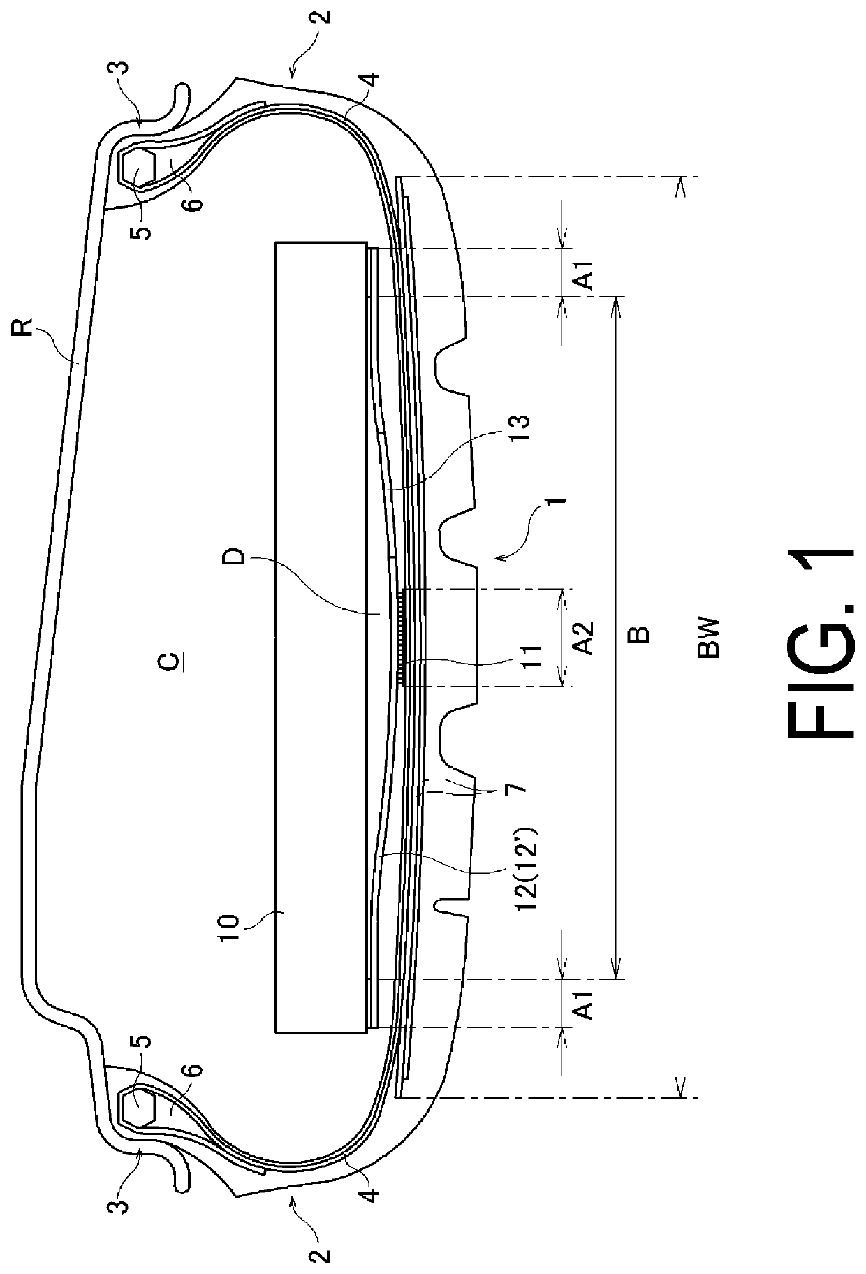
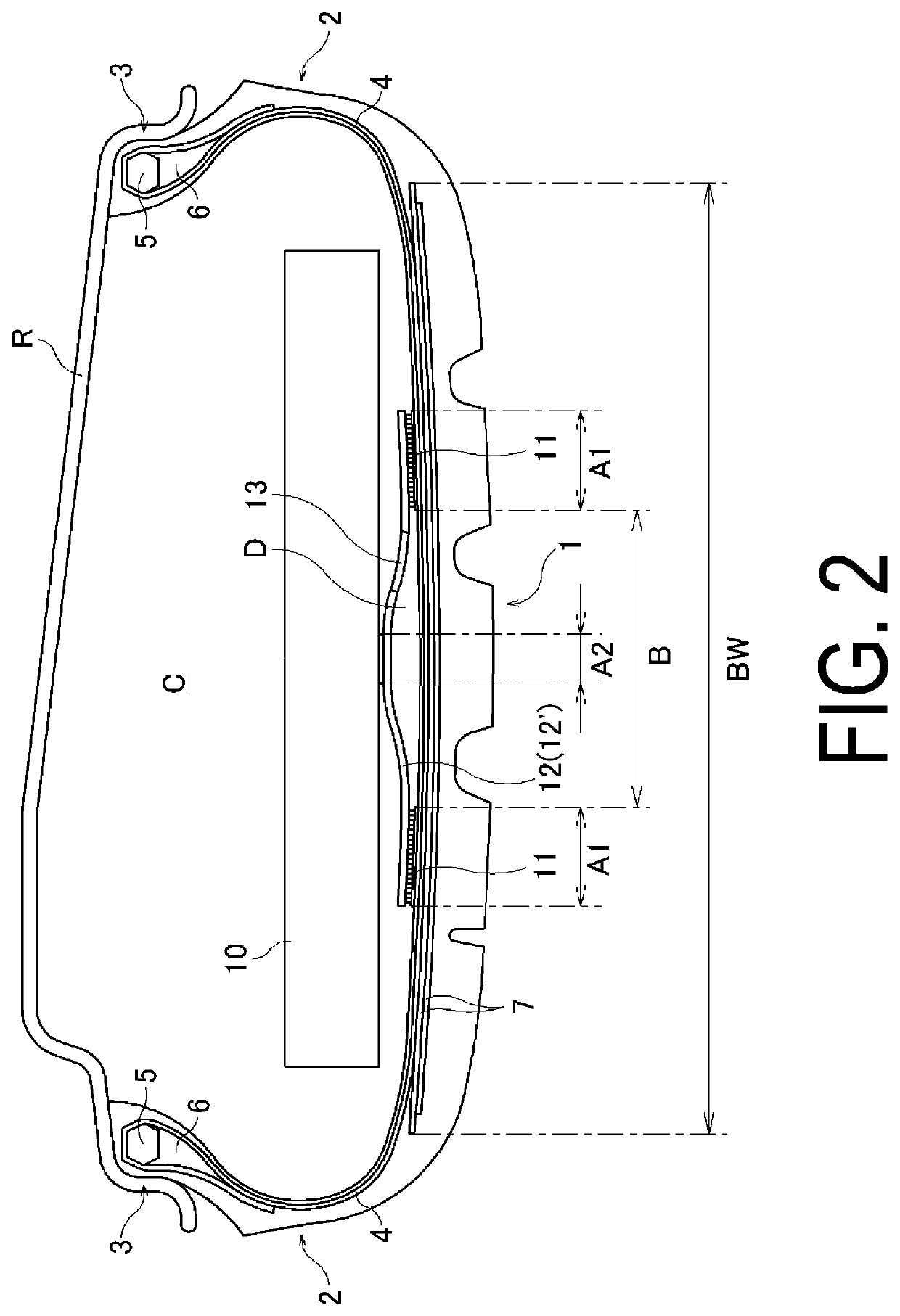
[0023]Configurations of embodiments of the present technology will be described in detail below with reference to the accompanying drawings.

[0024]As illustrated in FIGS. 1 and 2, a pneumatic tire of an embodiment of the present technology includes a tread portion 1, a pair of sidewall portions 2 respectively disposed on both sides of the tread portion 1, and a pair of bead portions 3 each disposed on an inner side in a tire radial direction of the pair of sidewall portions 2. R in the drawings represents a rim on which the pneumatic tire is mounted. Note that, FIGS. 1 and 2 are meridian cross-sectional views, and accordingly, although not illustrated, each of the tread portion 1, the sidewall portions 2, and the bead portions 3 extends in the tire circumferential direction to form an annular shape. Thus, the basic structure in a toroidal shape of the pneumatic tire is configured. Other tire components in the meridian cross-sectional view also extend in the tire circumferential direc...


PUM


Abstract

In a pneumatic tire, a sound absorptive member is installed on an inner surface of a tread portion with a sheet material interposed therebetween.The sheet material is fixed relative to the tire inner surface or the sound absorptive member at first fixed regions. The sheet material is not fixed relative to the tire inner surface or the sound absorptive member at a non-fixed region between the first fixed regions. The sheet material is fixed at a second fixed region relative to the other of the tire inner surface or the sound absorptive member ina portion of the non-fixed region. A repair liquid introducing portion connects a closed space and a tire cavity with the sheet material, the closed space being separated from the tire cavity by the tire inner surface and the non-fixed region or the sound absorptive member and the non-fixed region in a meridian cross-section.

Description

TECHNICAL FIELD[0001]The present technology relates to a pneumatic tire in which a sound absorptive member is installed on a tire inner surface, and particularly relates to a pneumatic tire that enables puncture repair without blocking a flow of puncture repair liquid by a sound absorptive member and a fixing means thereof.BACKGROUND ART[0002]In recent years, one proposed method of reducing tire noise (in particular, cavernous resonance caused by the vibration of the air filled in a cavity portion (tire cavity) formed in a tire when the tire is mounted on a rim) is to install a sound absorptive member formed of a porous material, such as a sponge, in the tire cavity. For example, in the example of Japan Unexamined Patent Publication No. 2005-138760, a sound absorptive member formed of a sponge material is bonded to an inner surface of a tread portion by an adhesive or double-sided tape.[0003]Meanwhile, when a tire mounted on a vehicle is punctured, a puncture repair liquid is inject...

Claims


Application Information

Patent Timeline
Patent Type & Authority Applications(United States)
IPC IPC(8): B60C19/00
CPCB60C19/002B60C19/122B60C3/04B60C9/28
Inventor WATABE, DAICHITANNO, ATSUSHI
Owner YOKOHAMA RUBBER CO LTD
Why Eureka
Try Eureka