Communication apparatus and program provided with failure determining method and function

a technology of communication apparatus and failure location, which is applied in the field of communication apparatus and related program provided with failure location determination method and function, can solve the problems of timeout error, timeout error, and timeout error in transmission detection, so as to reduce the time required to identify the failure location

Inactive Publication Date: 2009-06-16
FUJITSU LTD
View PDF8 Cites 0 Cited by
  • Summary
  • Abstract
  • Description
  • Claims
  • Application Information

AI Technical Summary

Benefits of technology

[0010]It is therefore an object of the present invention to provide a transmission apparatus and related program with a method and function for determining a failure, when a timeout error occurs, in order to locate the place of the causal failure location, narrowing down a range of the causal location to facilitate the cause investigation.
[0015]According to embodiments of the present invention, when a timeout error occurs, a failure location can be easily narrowed down based on time information of the last transmitted and received data left in a transmission apparatus and a reception apparatus and the time required to identify the failure location can be reduced over a conventional method.

Problems solved by technology

In these information systems, if the response information to the control information transmitted by a transmission apparatus cannot be obtained from the reception apparatus, the transmission detects a timeout error.
The timeout error is often caused by a failure location occurring in any one of the transmission apparatus, the reception apparatus and communication path connecting the transmission apparatus and the reception apparatus.
However, in prior art, if a transmission apparatus detects a timeout error, it is difficult to identify a failure location causing the error.
For example, if the timeout error occurs between a server and storage, the server cannot determine whether the cause of the error is: that the storage does not function, although the server has transmitted I / O instructions such as a read instruction and write instruction; that a communication path to the server has a problem, although the storage has transmitted the response information; or that an FC interface of the server is broken and the I / O instructions issued by the server has not been transmitted.
Therefore, if the timeout error between the server and the storage occurs on an end user's site where an information system was delivered, it takes time to identify the failure location.
In other words, a long time is needed for recovering the information system to a normal state, and it is problematic that a significant impact is placed on end users using the information system for business purpose.

Method used


Image

  • Communication apparatus and program provided with failure determining method and function
  • Communication apparatus and program provided with failure determining method and function
  • Communication apparatus and program provided with failure determining method and function

Examples


Embodiment Construction

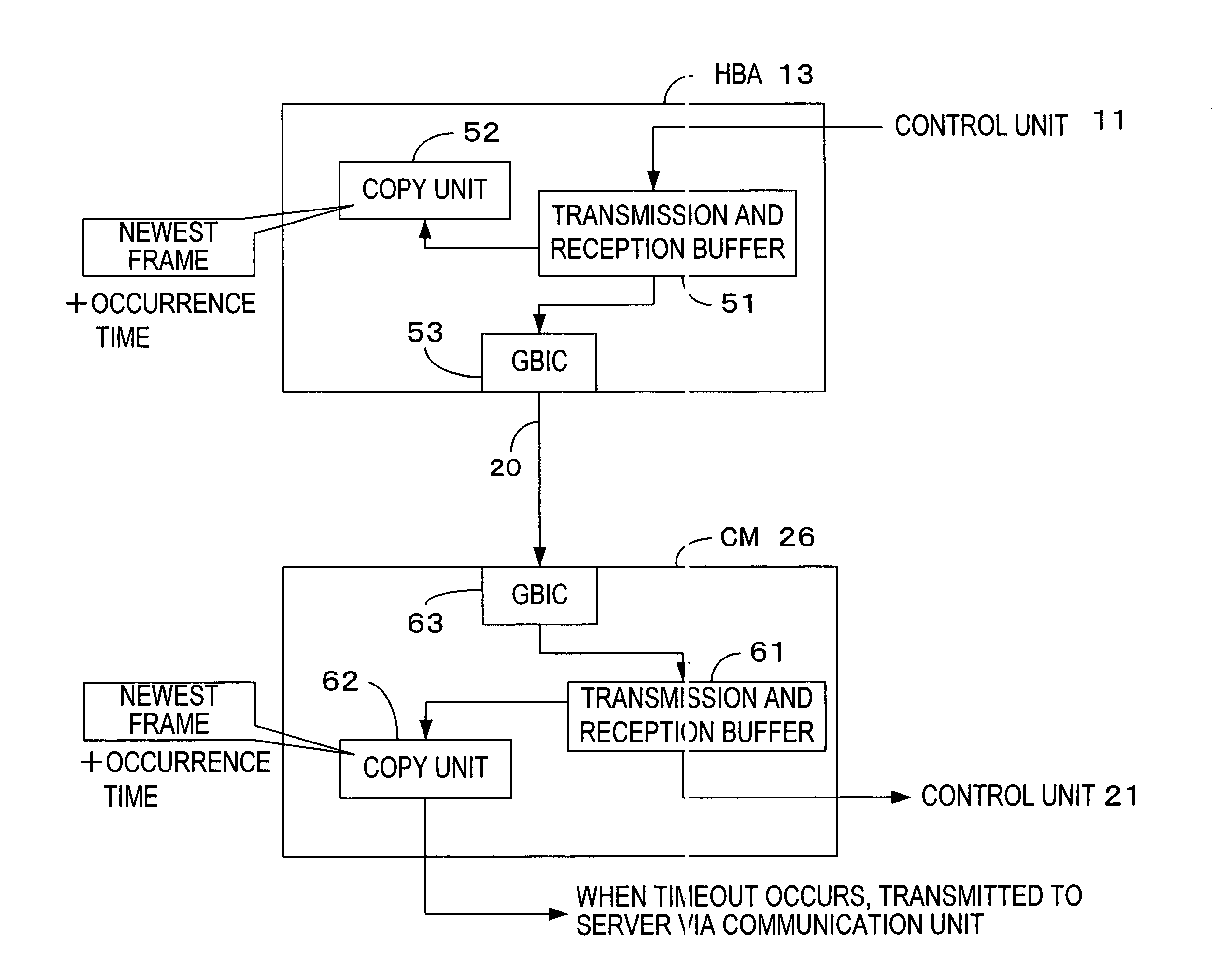
[0023]Embodiments of the present invention will now be described with reference to the accompanying drawings. However, the technical field of the present invention is not limited to the embodiments but covers the invention as defined in the claims and equivalents thereof.

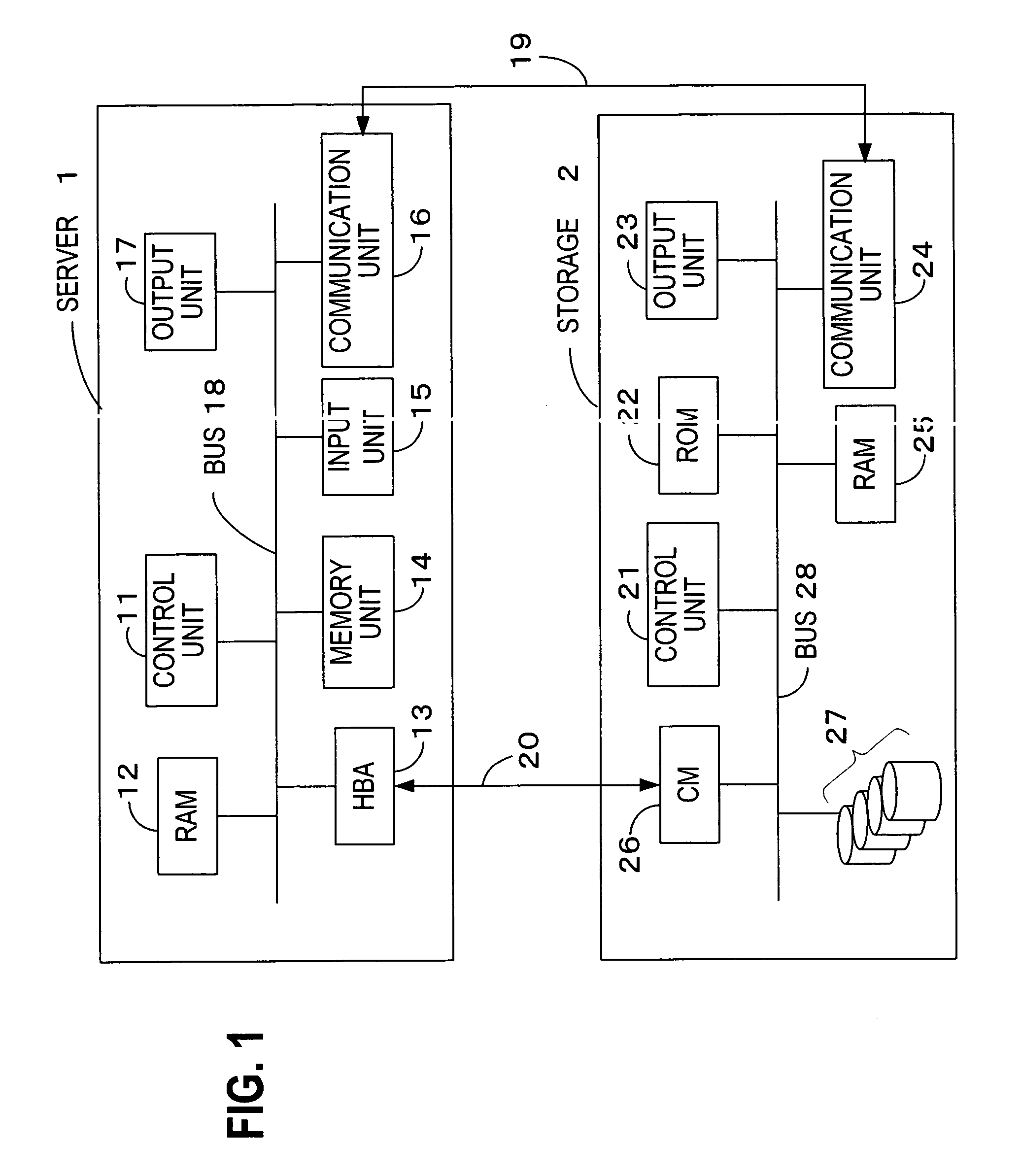
[0024]FIG. 1 is a configuration block diagram of an information system of the embodiment. The information system of the embodiment includes a server 1 and storage 2. The server 1 and the storage 2 are connected with a fiber channel cable (hereinafter, referred to as FC cable) 20 in order to control input and output of data stored in the storage 2 and are connected with a network cable 19 in order to control a control unit of the storage 2 from the server.

[0025]The server 1 of FIG. 1 includes a communication unit 16, a control unit 11, a RAM (Random Access Memory) 12, a memory unit 14, an input unit 15, an output unit 17, a HBA (Host Bus Adapter) 13 which are connected with each other via a bus 18. The communication ...


PUM


Abstract

Disclosed is a method of determining a failure in an information system including a transmission apparatus for transmitting control information and a reception apparatus connected to the transmission apparatus in such a manner as to enable information to be transmitted and received for receiving the control information, the reception apparatus transmitting response information to the received control information, wherein the transmission apparatus obtains, as first clock time, clock time of the most recently transmitted control information if the response information to the control information cannot be obtained within predetermined time period, wherein the transmission apparatus obtains, as second clock time, later one of clock time of the response information most recently transmitted by the reception apparatus and clock time of the control information most recently received by the reception apparatus, and wherein the transmission apparatus determines failure location based on the first clock time and the second clock time.

Description

BACKGROUND OF THE INVENTION[0001]1. Field of the Invention[0002]The present invention relates to a transmission apparatus and related program provided with a failure determining method and function for, when a failure occurs in an information system including a transmission apparatus transmitting control information and a reception apparatus transmitting response information to the control information and the causal location is to be found out, narrowing down a range of the causal location to facilitate the cause investigation.[0003]2. Description of the Related Art[0004]Generally, an information system consisting of a server, a client, storage and others has a transmission apparatus transmitting control information and a reception apparatus transmitting response information to the control information. For example, Japanese Patent Application Laid-Open Publication No. 1993-40744 describes an information system with a host computer transmitting a response frame (response information)...

Claims


Application Information

Patent Timeline
Patent Type & Authority Patents(United States)
IPC IPC(8): G06F11/00
CPCG06F11/0727G06F11/079H04L69/40H04L69/28G06F11/0757
Inventor OYAMA, KAZUHIKOHANADA, KOJI
Owner FUJITSU LTD
Why Eureka
Try Eureka