
Method for monitoring a steelmaking process and associated computer program

Pending Publication Date: 2022-06-09
ARCELORMITTAL INVESTIGACION Y DESARROLLO SL
View PDF0 Cites 0 Cited by
  • Summary
  • Abstract
  • Description
  • Claims
  • Application Information

AI Technical Summary

Benefits of technology

The patent text explains a new method for monitoring the process of making steel. The goal is to be able to do this in a way that works efficiently and accurately.

Problems solved by technology

It so reduces the accuracy of the modelling and limit the possibilities to reach the desired steel composition in an optimal way according to plant specificities.

Method used


Image

  • Method for monitoring a steelmaking process and associated computer program
  • Method for monitoring a steelmaking process and associated computer program

Examples


Embodiment Construction

[0040]With a method according to the invention it is possible to accurately determine the amount of each matter to be loaded into the steelmaking vessel and to optimize the steelmaking process in terms of reaching the required steel characteristics, matter consumption and energy savings.

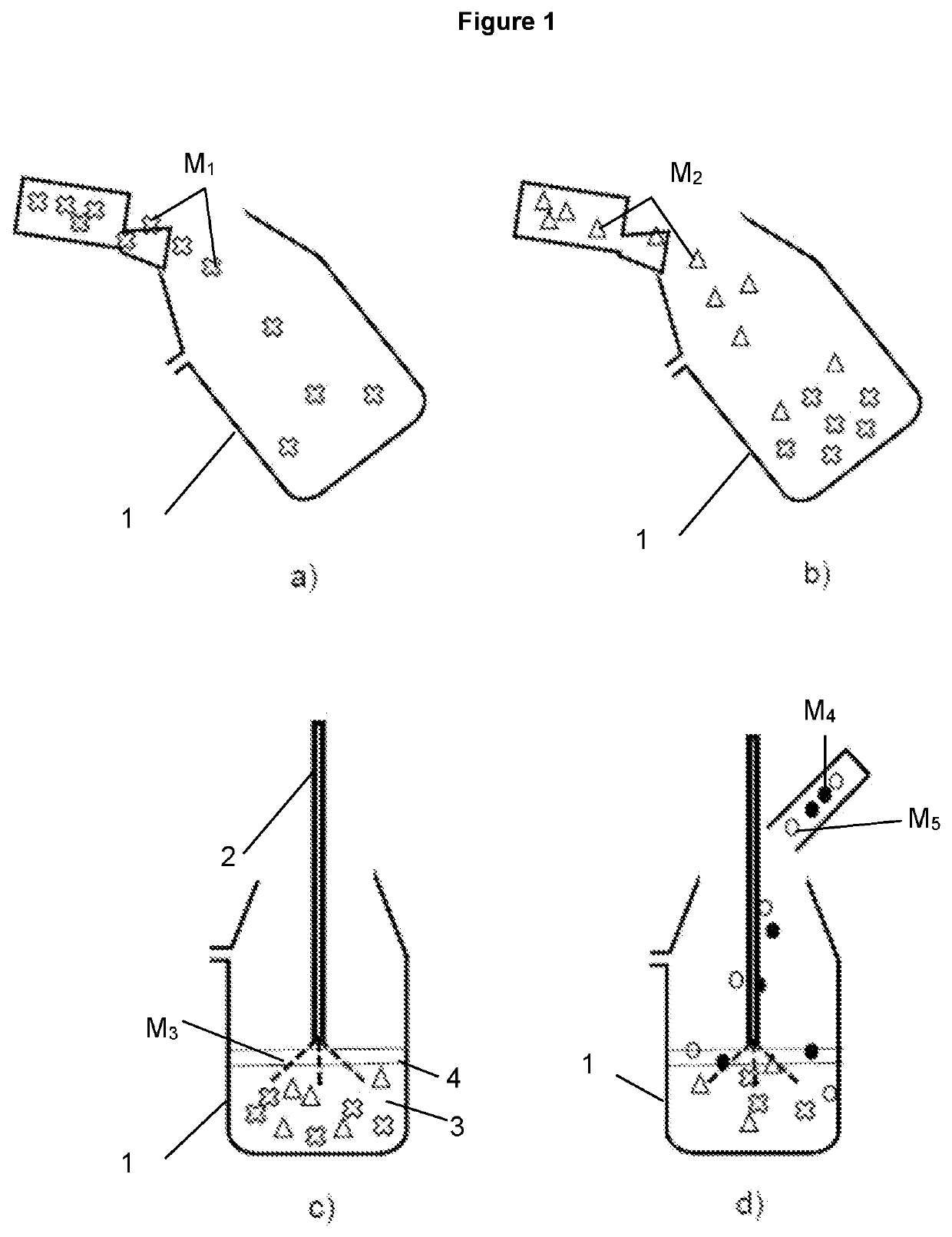
[0041]FIG. 1 illustrates the different steps of a steelmaking process in a specific steelmaking vessel named a converter 1. In a), a first matter M1, such as scrap, is charged into the converter 1. The converter 1 is in a tilted position to ease matter loading. In b), a second matter M2, such as hot metal is poured into the converter, still in a tilted position. In step c), the converter 1 has been moved to its standard vertical position and a lance 2 is inserted into the converter to inject a third matter M3, which may be oxygen. Oxygen could be injected in other manner than with a lance, for example through a tuyere located for example in the bottom of the converter. The step of injecting oxygen is...


PUM

PropertyMeasurementUnit
Temperatureaaaaaaaaaa
Weightaaaaaaaaaa
Basicityaaaaaaaaaa

Abstract

A monitoring method of a steelmaking process in a steelmaking vessel, wherein matters Mn, each having its respective properties PMn, are charged into said steelmaking vessel so as to produce a liquid steel and a slag.

Description

[0001]The invention is related to a method for monitoring a steelmaking process and to a computer program including software instructions allowing to perform such a method.BACKGROUND[0002]Steel can be manufactured through two different routes. The first route consists in producing hot metal from a blast furnace and then transforming said hot metal into steel by decarburization in an oxygen converter. The second route consists in melting ferrous scraps in an Electric Arc Furnace (EAF) to directly produce steel.[0003]According to the first route, hot metal from blast furnace is poured into a hot metal ladle which is then poured into a converter (or BOF for Basic Oxygen Furnace) in which scrap have been previously loaded. Oxygen is blown into the converter, for example with a lance, to allow decarburization of hot metal and its transformation into liquid steel. Slag, named converter slag, is a by-product of such a reaction.[0004]Decarburisation reaction releasing energy, scrap are usua...

Claims


Application Information

Patent Timeline
IPC IPC(8): C21C5/36C21C5/54
CPCC21C5/36C21C2005/5288C21C2300/06C21C5/54C21C2200/00Y02P10/25Y02P10/20F27D19/00F27D2019/0003
Inventor WAGNER, DAMIENHUBER, JEAN-CHRISTOPHE
Owner ARCELORMITTAL INVESTIGACION Y DESARROLLO SL
Learn More