Architectural wall

a technology for building walls and walls, applied in the field of architectural walls, can solve the problems of not particularly devised exterior walls, and achieve the effect of enhancing heat insulating properties and preventing dew condensation

Pending Publication Date: 2022-06-09
SASAKI BEJI
View PDF0 Cites 0 Cited by
  • Summary
  • Abstract
  • Description
  • Claims
  • Application Information

AI Technical Summary

Benefits of technology

[0057]According to one aspect of the present invention, it is possible to provide the exterior wall panel that allows an air layer to be formed between the inner member and the exterior wall part. In addition, heat insulating properties are enhanced, and dew condensation can also be prevented.

Problems solved by technology

However, the exterior wall is not particularly devised.

Method used


Image

  • Architectural wall
  • Architectural wall
  • Architectural wall

Examples


Embodiment Construction

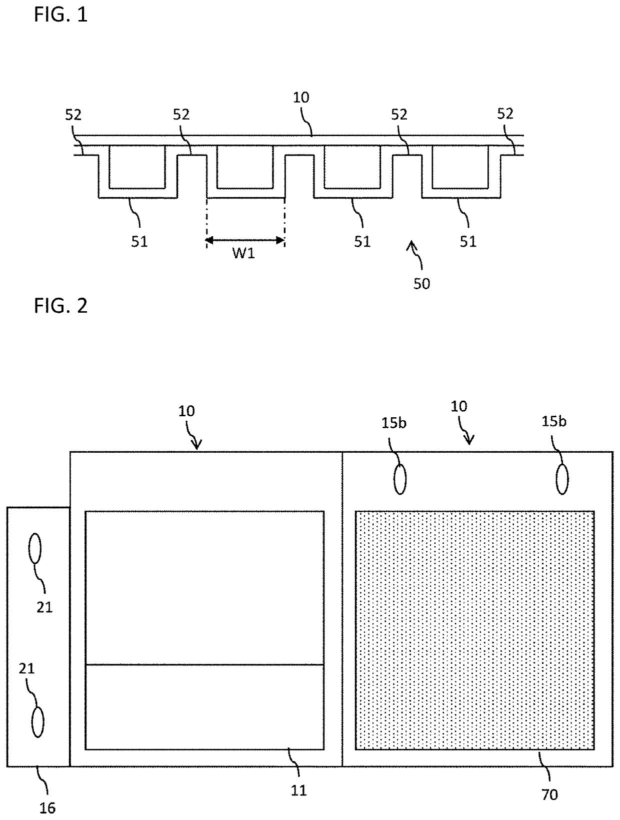
[0081]The architectural wall according to the present embodiment is, for example, an exterior wall panel. The exterior wall panel may be connectable to another exterior wall panel laterally or in a vertical direction. In the present embodiment, “upper” means an upper side when the exterior wall panel is installed in a building, and “lower” means a lower side when the exterior wall panel is installed in a building. In the present embodiment, “lateral” means a direction orthogonal to the vertical direction, and typically means a direction orthogonal to the vertical direction and in which the surface of the exterior wall panel extends.

[0082]As illustrated in FIG. 1, according to the present embodiment, the exterior wall panel may have an inner member 10 and an exterior wall part 50 that is provided on the outer side of the inner member 10 and has a plurality of outwardly projecting parts 51 for forming a ventilation passage with the inner member 10. The outwardly projecting part 51 may...


PUM


Abstract

An architectural wall that allows an air to flow between an inner member and an exterior wall part is provided.An architectural wall comprising an inner member 10; and an exterior wall part 50 that is provided on an outer side of the inner member 10 and forms a space where air enters between the exterior wall part 10 and the inner member 50.

Description

TECHNICAL FIELD[0001]The present invention relates to an architectural wall that constitutes an exterior wall of a building.BACKGROUND ART[0002]Conventionally, it is known to use an exterior wall panel. For example, Patent Literature 1 discloses that a building unit has a plurality of columns and upper and lower girders, and these columns and girders are connected in a cubic shape, a first panel is pre-fixed, at a unit manufacturing factory, to an exterior wall surface opening to which an exterior wall panel is attached in a completed building state among four unit openings surrounded by the columns and the girders, and a second panel to be attached to a structure other than the building unit in the completed building state is temporarily fixed. However, the exterior wall is not particularly devised.CITATION LISTPatent Literature[0003]Patent Literature 1: JP 2011-202439 ASUMMARY OF INVENTIONProblem to be Solved by Invention[0004]The present invention provides an architectural wall t...

Claims


Application Information

Patent Timeline
Patent Type & Authority Applications(United States)
IPC IPC(8): E04F13/08E04F13/12
CPCE04F13/0869E04F13/12E04F13/0894E04F13/0871E04B1/7645
Inventor SASAKI, BEJI
Owner SASAKI BEJI
Why Eureka
Try Eureka