Injection Pump

a technology of injection pump and injection chamber, which is applied in the direction of machines/engines, liquid fuel engines, and positive displacement liquid engines, etc., can solve the problems of difficulty in managing the additive rate and volume, and achieve the effects of reducing the mechanical footprint of the unit, preventing premature sealing wear, and increasing protection

Pending Publication Date: 2022-06-09
TEXAS INJECTION CORP
View PDF6 Cites 0 Cited by
  • Summary
  • Abstract
  • Description
  • Claims
  • Application Information

AI Technical Summary

Benefits of technology

[0006]In accordance with one aspect of the invention, the pump apparatus disclosed herein features an advanced head technology, which includes an enclosed, spring energized seal, interior wiper, no backside suction, and additional seal protection providing increase protection from water and dust ingress. The spring enlarged seal further protects the pump by preventing premature seal wear and unnecessary user error, such as overtightening packing. The provision of a duplex pump head configuration provides the opportunity to reduce the mechanical footprint of the unit and optimize efficiency by utilizing a single motor while doubling injection capability. Fluid flow efficiency is also further maximized by proprietary bubble tight check valves used in the pump unit.

Problems solved by technology

While there are many different injection pump designs and apparatus known in the art, one drawback relates to difficulties in managing the rate and volume of additive to be injected without changing the power input driving the pump piston, which may also be referred to as a plunger herein.

Method used


Image

  • Injection Pump
  • Injection Pump
  • Injection Pump

Examples


Embodiment Construction

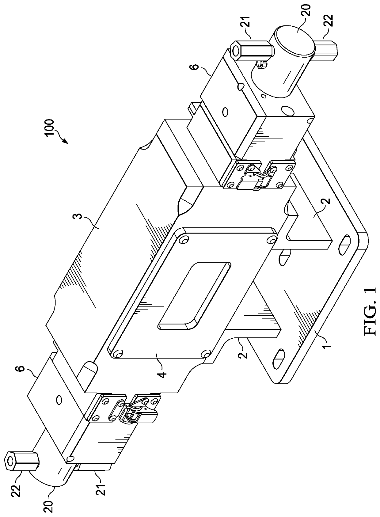
[0012]As illustrated in FIG. 1, pump assembly 100 according to the invention comprises main body 3 which houses plunger carriage assembly 10 (shown in FIGS. 2 and 3) with attached pump head adjuster blocks 6, pump heads 20 with attached suction valves 21 and discharge valves 22. Main body 3 may be supported and secured to a fixed object or surface with the attachment of base plate 1 to the fixed object or surface. Base legs 2 operate to secure the main body 3 to base plate 1. Face plate 4 and clear plate 5 are attached to main body 3 with screws and may be detached to provide access to the internal components of the plunger carriage assembly 10 for maintenance and parts replacement from time to time. Clear plate 5 allows a user to visually inspect the components housed in main body 3 without the need to remove face plate 4 to visually inspect the components housed in main body 3.

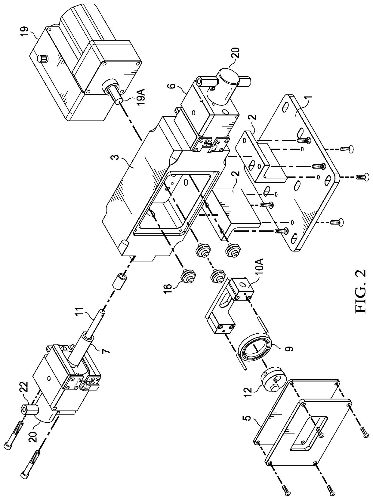
[0013]FIG. 2 is an exploded view of main body 3 housing plunger carriage assembly 10 components comprisin...


PUM


Abstract

The present invention is directed to an improved liquid additive injection pump that of a type wherein a variety of additive volumes may be metered into a fluid stream or fluid source by adjusting the plunger stroke with an easily accessible adjustment bushing without changing or interrupting, the power supplied to the pump during operation. A robust roller bearing drive is used to power the plunger(s) providing fluid suction and discharge as the plunger(s) cycle, while ensuring accurate and reliable additive injection rates. A spring energized seal eliminates overtightened packing by field technicians. An easily accessible adjustment bushing allows the user to modify the piston stroke length, thereby increasing, decreasing or stopping the volumetric flow of injected additive into a fluid stream or storage container.

Description

CROSS-REFERENCE TO RELATED APPLICATIONS[0001]This application claims the benefit of U.S. Provisional Patent Application Ser. No. 63 / 121,312 filed Dec. 4, 2020, and entitled “Injection Pump”, which is incorporated herein by reference in its entirety.BACKGROUND OF THE INVENTION[0002]Electric and other types of injection pump machinery are used to inject additives into a diverse array of fluids. While there are many different injection pump designs and apparatus known in the art, one drawback relates to difficulties in managing the rate and volume of additive to be injected without changing the power input driving the pump piston, which may also be referred to as a plunger herein. As such, a need exists for an improved injection pump which provides the ability to easily adjust the volumetric flow rate the of injected liquid discharged from the injection pump without the need to increase, decrease or stop the pump power supply during operation.SUMMARY OF THE INVENTION[0003]The present i...

Claims


Application Information

Patent Timeline
Patent Type & Authority Applications(United States)
IPC IPC(8): F04B53/10F04B53/16F04B53/00
CPCF04B53/109F04B53/007F04B53/164F04B49/125F04B1/07F04B1/053
Inventor WARREN, MICHAEL TODD
Owner TEXAS INJECTION CORP
Why Eureka
Try Eureka