System and method for determining 3D surface features and irregularities on an object
a technology of surface features and irregularities, applied in the field of machine vision systems, to achieve the effect of minimal cost and minimal cos
- Summary
- Abstract
- Description
- Claims
- Application Information
AI Technical Summary
Benefits of technology
Problems solved by technology
Method used
Image

Examples
Embodiment Construction
I. System Overview
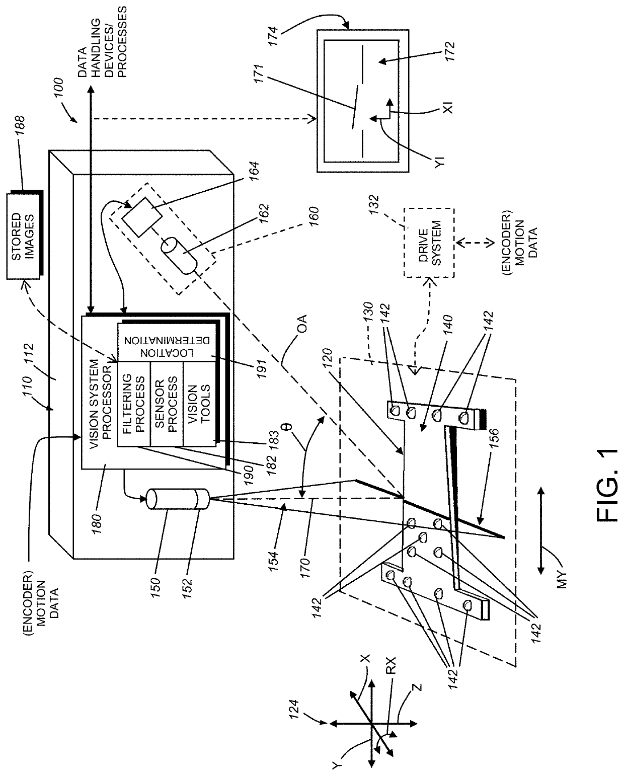
[0025]FIG. 1 shows a vision system arrangement 100 including a laser displacement sensor assembly 110 oriented to image an object 120 (also sometimes referred to as a “part”). The displacement sensor assembly (or, simply “displacement sensor”) can be contained in a single housing 112 that is mounted at an appropriate location with respect to the imaged scene. In alternate embodiments, the displacement sensor can comprise discrete, separated subcomponents. The object 120 and the displacement sensor 110 are in relative motion (double arrow MY) with either the displacement sensor 110, the object 120, or both, moving (the scan motion direction) along at least one axis of the relative coordinate system 124 (in this example, the physical y-axis direction). In a typical arrangement, the object 120 is located on a precision motion stage 130 (shown in phantom) that provides motion data from an encoder or similar device operatively connected to the motion stage drive system ...
PUM
 Abstract
Description
Claims
Application Information
 - R&D Engineer
- R&D Manager
- IP Professional
- Industry Leading Data Capabilities
- Powerful AI technology
- Patent DNA Extraction
Browse by: Latest US Patents, China's latest patents, Technical Efficacy Thesaurus, Application Domain, Technology Topic.
© 2024 PatSnap. All rights reserved.Legal|Privacy policy|Modern Slavery Act Transparency Statement|Sitemap