Object counting method and surveillance camera

Pending Publication Date: 2022-06-09
VIVOTEK INC
View PDF4 Cites 0 Cited by
  • Summary
  • Abstract
  • Description
  • Claims
  • Application Information

AI Technical Summary

Benefits of technology

The present invention provides a method for automatically counting objects using a surveillance camera. By analyzing the movement of objects in the camera's field of view, the method can accurately determine the number and direction of object movement, without requiring manual adjustment of the camera's settings. This saves time and increases accuracy, making it easier to analyze surveillance footage.

Problems solved by technology

Thus, design of an object counting method capable of automatically detecting and identifying an entering trace and a leaving trace relevant to the surveillance region is an important issue in the surveillance camera industry.

Method used


Image

  • Object counting method and surveillance camera
  • Object counting method and surveillance camera
  • Object counting method and surveillance camera

Examples


Embodiment Construction

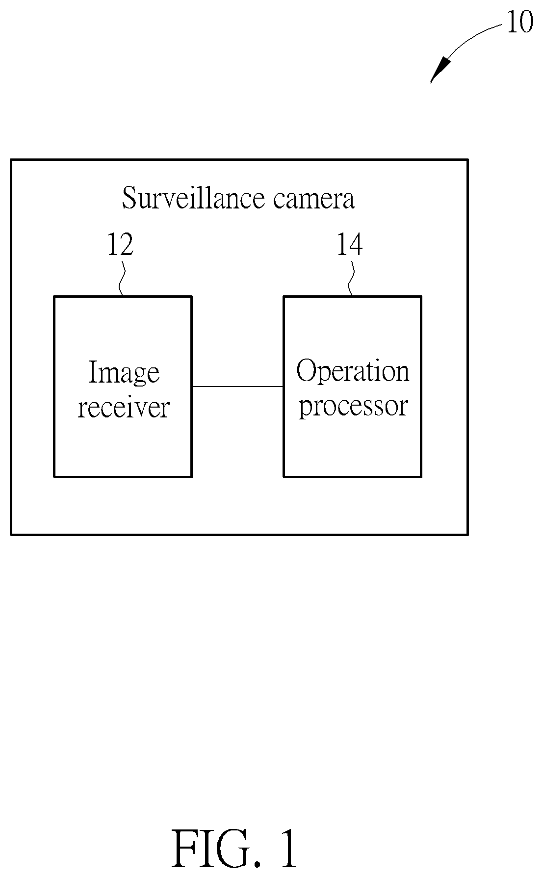
[0012]Please refer to FIG. 1. FIG. 1 is a functional block diagram of a surveillance camera 10 according to an embodiment of the present invention. The surveillance camera 10 can be installed on a variety of environments, such as an inlet of a shop, a train or a bus, and used to count a number of a target object, which means human, without setting or adjusting specific parameter of the surveillance camera 10 based on the environment. The surveillance camera 10 can be a two dimensional camera used to compute a geometrical center of a human pattern within a surveillance image to be a trace point. The geometrical center may be a mass center or a gravity center of the human pattern. The surveillance camera 10 can further be a three dimensional camera used to acquire depth information of the target object from the surveillance image, and estimate a foot position from a head of the target object to be the trace point. Application of the surveillance camera 10 is not limited to the above-m...


PUM


Abstract

An object counting method is applied to a surveillance camera and used to determine an amount and a direction an object passing over a surveillance region. The object counting method includes acquiring a plurality of known traces, dividing the plurality of known traces into a first group passing the surveillance region along a first direction and a second group passing the surveillance region along a second direction, computing a first start point computed value of the first group and a second start point computed value of the second group to acquire a start point connection vector, and comparing the start point connection vector with a trace vector of a target object to determine whether the target object passes over the surveillance region along the first direction or the second direction.

Description

BACKGROUND OF THE INVENTION1. Field of the Invention[0001]The present invention relates to an object counting method and a related surveillance camera, and more particularly, to an object counting method capable of reducing manual control process for automatically accurate analysis and a related surveillance camera.2. Description of the Prior Art[0002]Traffic analysis technique is used to count a number of the customer in the shop or a number of the vehicle in the road. The customer passes over a specific door is defined as one counting datum. For determining whether a target object passes over the specific door, the conventional traffic analysis technique draws a flow channel corresponding to the specific door within the image, and any target object passes over the specific door can increase the counting number. However, the conventional traffic analysis technique draws the flow channel in accordance with a shape and a size of the specific door. If the surveillance camera is transf...

Claims


Application Information

Patent Timeline
IPC IPC(8): G06V20/52G06T7/66G06T7/50G06T7/70G06T7/215G06K9/62H04N7/18
CPCG06V20/52G06T7/66G06T7/50G06T7/70G06T7/215G06V2201/07H04N7/188H04N7/183G06T2207/30242G06T2207/30232G06T2207/30196G06K9/6215G06T7/246G06T2207/30241G06F18/22
Inventor LIU, CHENG-CHIEH
Owner VIVOTEK INC
Why Eureka
Try Eureka