Coaxial RF connector

a technology of rf connector and coaxial connector, which is applied in the direction of coupling device connection, two-part coupling device, electrical apparatus, etc., can solve the problem that the coaxial hv (high voltage) connector is in most cases not suitable for rf signals

Active Publication Date: 2022-06-09
SPINNER
View PDF0 Cites 0 Cited by
  • Summary
  • Abstract
  • Description
  • Claims
  • Application Information

AI Technical Summary

Benefits of technology

[0014]In a further embodiment, the outer conductor has a reinforced section which may be distant from the slits and oriented away from the outside or contacting side of the connector. This reinforced section may enhance stability of the outer conductor and the connector. It may further provide means configured to hold a connector housing. Furthermore, the reinforced section may provide support for the spring element. It may have an edge configured to support the spring element such that the spring element is arranged between the edge and the contact sleeve. The reinforced section may also hold the locking sleeve in position. The reinforced section may have a cylindrical outer shape. It may have further protrusions or recesses configured to hold the locking sleeve. It may hold the locking sleeve in a radial direction relative to the center axis.
[0015]The spring-loaded contact elements may have a contact element protrusion which may be oriented in a radial direction and which may interface with a contact sleeve protrusion to limit an axial movement of the contact sleeve preferably in an outward direction. In an unconnected state of the connector, the spring element presses the contact sleeve in an outward direction of the connector. If the outward movement is limited by the two interfacing protrusions, the contact sleeve cannot fall off the connector.
[0020]This embodiment provides a significantly more precise and reliable outer connector contact, even, if there is a minor misalignment between the connectors. Such a misalignment may be compensated by the contact sleeve.
[0024]In a further embodiment, both the centering face and the centering ring have a length that is sufficient to prevent tilting between the connectors and to prevent an additional load by tilting on the contact system.
[0028]In an embodiment, a coaxial RF connector is a connector configured to electrically connect RF lines and to couple radio frequency (RF) signals. An outer conductor is arranged coaxially around an inner conductor. For coupling such RF signals, the connector must have a predetermined characteristic impedance which may be 50 Ohm. The connector must also have low insertion losses and low return losses. This requires beyond a high conductivity, a coaxial RF connector to have a conductor structure which maintains the characteristic impedance over the full length of the connector with minimal deviations. This means that essentially the capacitance must be constant over the full length of the connector. Therefore, at each point of the conductor structure, a certain relation between the diameter of the inner conductor and the distance between outer conductor and inner conductor must be maintained. Here, also the dielectric constant of a material between the inner conductor and the outer conductor must be considered.
[0029]Coaxial HV (high voltage) connectors are in most cases not suitable for RF signals. Such HV connectors provide a symmetrical, coaxial structure to maintain an even field distribution, but it is not essential to have a certain characteristic impedance and further to maintain such a characteristic impedance constant over the full length of the connector. Therefore, the design of HV connectors is less critical.

Problems solved by technology

Coaxial HV (high voltage) connectors are in most cases not suitable for RF signals.

Method used


Image

  • Coaxial RF connector
  • Coaxial RF connector
  • Coaxial RF connector

Examples


Embodiment Construction

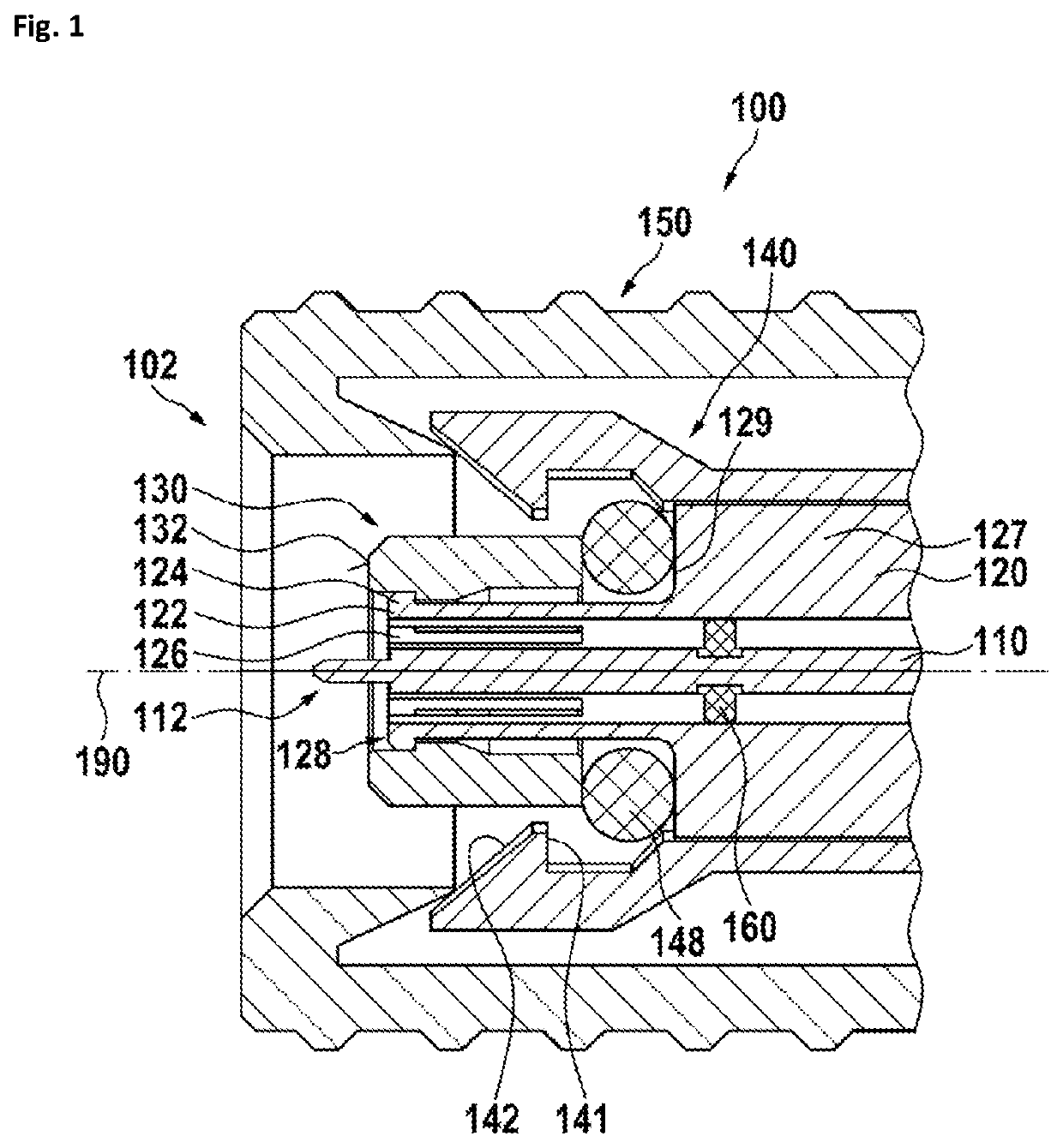
[0042]In FIG. 1, a first embodiment of a coaxial RF connector 100 is shown. The coaxial RF connector 100 has a contact side 102—to the left of the figure—to which a counter connector (not shown) may be connected. The coaxial RF connector 100 has an inner conductor 110 and arranged coaxially thereto an outer conductor 120. The inner conductor 110 defines a center axis 190. In this embodiment, the inner conductor is part of a male connector and therefore has an inner conductor contact pin contact pin 112. The inner conductor may be supported within the outer conductor by at least one strut 160.

[0043]The outer conductor has an outer conductor end face 122 at the end of the outer conductor and oriented towards the contact side 102. The outer conductor further has a plurality of longitudinal slits 126 extending from the outer conductor end face. The remaining material between these slits form spring-loaded contact elements which may produce a contact force in a radial direction with resp...


PUM


Abstract

A coaxial RF connector with inner and outer conductors has an outer conductor with a plurality of longitudinal slits forming a plurality of spring loaded contact elements. A contact sleeve is arranged movable in axial direction surrounding coaxially the outer conductor. The contact sleeve has a radial contact face which is in contact with the spring loaded contact elements and an axial contact face which has a plane orthogonal to the center axis of the connector for contacting a counter connector.

Description

BACKGROUND1. Field of the Invention[0001]The invention relates to a coaxial connector for radio frequencies (RF), which may be a miniature connector.2. Description of Related Art[0002]U.S. Pat. No. 9,236,694 B2 discloses a coaxial connector system designed for low passive intermodulation. A plug connector has a spring-loaded outer connector for contacting the solid side wall of a socket connector. Due to a precision contact de-sign and high contacting forces between the plug connector and the second connector, a low passive intermodulation is achieved.[0003]This spring loaded outer connector can hardly be miniaturized to very small connector sizes which are required for frequencies in a range above 20 GHz.SUMMARY[0004]The problem to be solved by the invention is to provide a coaxial RF connector having an outer conductor Furthermore, the RF connector may be miniaturized, for example. An outer connector may have a diameter in a range of less than 2 mm. The connector should be robust ...

Claims


Application Information

Patent Timeline
Patent Type & Authority Applications(United States)
IPC IPC(8): H01R13/629H01R24/44
CPCH01R13/629H01R2103/00H01R24/44H01R13/2464H01R13/633H01R13/2407H01R13/2414H01R24/40
Inventor GRABICHLER, ANDREASZISSLER, WOLFGANGNEUMAIER, CHRISTOPH
Owner SPINNER
Why Eureka
Try Eureka